STM32 #14: Reading raw blocks on a microSD with SPI
The last post finally finished the SD card initialisation sequence. The card left idle state using CMD55 + ACMD41, CMD58 returned a valid OCR value, and I used CMD9 and CMD10 to read the CSD and CID registers. This proves a few core foundations:
- The card can be initialised into SPI mode.
- The driver can detect SDHC/SDXC block addressing.
- The driver can read register data after a
0xFEdata token. - The SPI command/response layer is working with some reliability.
Now it’s time to stop asking the card about itself and try to read some storage. However, this post still won’t be using FatFS. Before adding that, I want to prove out the low level drivers and their functions fully before integrating them into the FatFS layer. We need to prove that the sd driver can read and write a single raw 512 byte block. If this works, then the eventual FatFS layer should be easier, because disk_read() and disk_write() should be able to be simple translation wrappers to the lower level sd card driver.
Why bother with raw blocks for FatFS
FatFS does the filesystem work for us. It knows how to create files, find free clusters, update FAT tables, and manage directories. FatFS still needs the low level drivers to provide the actual sector access. The application layers will look like the ones posted in STM32 #12: Talking to a microSD card over SPI. So first we need to build and prove out two core functions:
sd_status_t sd_card_read_block(uint32_t block_index, uint8_t *buffer);
sd_status_t sd_card_write_block(uint32_t block_index, const uint8_t *buffer);
This post we will just build the read_block function.
Block addressing
For SDHC/SDXC cards, the address passed to CMD17 (Read a block) and CMD24 (write a block) is a 512 byte block number. For older cards, the address is a byte address. For example, if we wanted to access block 100 000:
- SDSC address = 100 000 * 512
- SDHC/SDXC address = 100 000
Let’s create a simple helper to abstract that conversion away:
static uint32_t sd_block_to_card_address(uint32_t block_index) {
    if (sd_card_type == SD_CARD_TYPE_SDHC_OR_SDXC) {
        return block_index;
    }

    return block_index * SD_BLOCK_SIZE;
}
Now the rest of the driver can work in logical 512 byte block numbers.
Commands and Macros for Writing and Reading Blocks
Here are the commands we will focus on:
| CMD | Meaning | Command byte |
|---|---|---|
| CMD17 | Read single block | 0x40 bitwiseOR 17 = 0x51 |
| CMD24 | Write single block | 0x40 bitwiseOR 24 = 0x58 |
Here are some macros that will help us use these commands in an easy to understand way:
#define SD_CMD17 17u // Read single block

#define SD_BLOCK_SIZE 512u
#define SD_DATA_TOKEN 0xFEu

#define SD_CRC_SIZE 2u

#define SD_DATA_RESPONSE_MASK 0x1Fu
#define SD_DATA_ACCEPTED 0x05u

#define SD_WRITE_BUSY_ATTEMPTS 10000u
The SD_DATA_TOKEN was covered in the last post but I’m keeping it here for brevity. It is used at the beginning of a block read, and for block writes the host sends it before the 512 byte payload. The full sequence is:
- Select the card
- Send
CMD17with block address - Wait for an R1 response
- Wait for the 0xFE data token
- Read 512 bytes
- Read 2 CRC bytes
- Deselect the card
So let’s create a function following that sequence:
sd_status_t sd_card_read_block(uint32_t block_index,
                               uint8_t *buffer) {

        if ( buffer == NULL ) { return SD_ERR_PARAM; }

        // Setup parameters
        uint32_t address = sd_block_to_card_address(block_index);
        uint8_t r1 = 0xFFu;

        // Select the card
        sd_select();

        // Send read single block command
        sd_status_t status = sd_write_command_packet(SD_CMD17,
                                                     address,
                                                     SD_DUMMY_CRC);
        if (status != SD_OK) {
                sd_deselect();
                return status;
        }

        // Wait for R1 response
        status = sd_wait_r1(&r1);
        if (status != SD_OK) {
                sd_deselect();
                return status;
        }
        if (r1 != SD_R1_READY_STATE) {
                sd_deselect();
                return SD_ERR_BAD_RESPONSE;
        }

        // Wait for data token
        status = sd_wait_data_token();
        if (status != SD_OK) {
                sd_deselect();
                return status;
        }

        // Read data
        status = sd_read_bytes(buffer, SD_BLOCK_SIZE);
        if (status != SD_OK) {
                sd_deselect();
                return status;
        }

        // Read CRC bytes
        uint8_t crc[SD_CRC_SIZE];
        status = sd_read_bytes(crc, sizeof(crc));
        if (status != SD_OK) {
                sd_deselect();
                return status;
        }

        // Deselect the card
        sd_deselect();
        return SD_OK;
}
This was pretty straight forward because of the way we set this up in the last post with sd_write_command_packet(), sd_wait_r1(), sd_wait_data_token(), and sd_read_bytes() all being reused.
Reading block 0
Block 0 should contain a master boot record, partition table or filesystem boot sector depending on how the card has been formatted. Let’s just confirm we get 512 bytes back first.
Now there are again two ways to test this, by calling the previous UART print functionality developed, or to use a logic analyzer. You can write some code to convert the block to hex and print to the UART, for now I’m just going to show you the logic analyser, because we can directly tap into the MISO line and check the block bytes being sent back by the SD card, which will be a solid confirmation of the protocol implementation. So to test this my main code will have this snippet, you’ll have to make sure SD_BLOCK_SIZE is in the sd_card.h file or main to make it publicly accessible.
    // SD Card - Init
    uint8_t block[SD_BLOCK_SIZE];
    sd_status_t status = sd_card_init();
    if (status != SD_OK) {
        bsp_uart1_write_string("SD init failed\r\n");
        while (1) {}
    }

    // SD Card - Read block 0
    status = sd_card_cmd17_read_block(0u, block);
    if(status != SD_OK) {
        bsp_uart1_write_string("Read block 0 failed");
        while (1) {}
    }
    bsp_uart1_write_string("Block read OK\r\n");
It’s a good sign if both pass and do not report an error over UART. I’ve also added a bit to print out the first 64 bytes of the block to check it’s not empty:
    // Print block read on uart
    debug_uart_print_hex_buffer("BLOCK0[0:64]", block, 64u);
    while (1) {}
The while loops just make it easier to read the UART and are not integral.
The UART output works but let’s get the logic analyser on it to take a look at the whole block and check the protocol sequence:
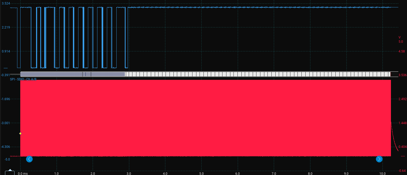
There is a lot here but a quick poke around shows everything seems to be in order, here is the initialisation sequence and the read block request, remember the command packet is 6 bytes, everything else is a dummy clock, here is a printout of the logic analyser decoding, I;’ve tried to split it up to make it easier to read:
 FF FF FF FF FF FF FF FF FF FF // 80 clock dummy bytes
 40 00 00 00 00 95             // CMD0 + CRC
 FF FF FF                      // Wait on CMD0
 48 00 00 01 AA 87             // CMD8
 FF FF FF FF FF FF FF          // Dummy blocks to read R1 + R7
 77 00 00 00 00 FF             // CMD55
 FF FF FF                      // Dummy clocks
 69 40 00 00 00 FF             // ACMD41
 FF FF FF                      // Dummy clocks
 77 00 00 00 00 FF             // Repeated CMD55 + ACMD41 Loop
 FF FF FF
 69 40 00 00 00 FF
 FF FF FF
 77 00 00 00 00 FF
 FF FF FF
 69 40 00 00 00 FF
 FF FF FF
 7A 00 00 00 00 FF
 FF FF FF FF FF FF FF
 51 00 00 00 00 FF             // CMD17 - Read block 0
 FF FF FF ... // Lots of FF to clock out the block data
The MOSI line shows the expected init sequence and then sends CMD17 for block 0. The actual proof of the read comes from MISO, where the card should return R1 = 0x00, then a 0xFE data token, then 512 bytes of block data followed by two CRC bytes:
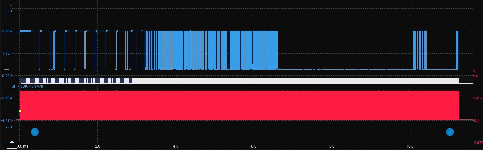
Here is the decoded output:
FF FF FF FF FF FF FF FF
FF FF FF FF FF FF FF FF FF
01
FF FF FF FF FF FF FF FF
01 00 00 01 AA FF
FF FF FF FF FF FF FF
01
FF FF FF FF FF FF FF FF
01
FF FF FF FF FF FF FF FF
01
FF FF FF FF FF FF FF FF
01
FF FF FF FF FF FF FF FF
01
FF FF FF FF FF FF FF FF
00                               // ACMD41 R1 response ready
FF FF FF FF FF FF FF FF
00 C0 FF 80 00                   // CMD58 response R1 + OCR register
FF FF FF FF FF FF FF FF
00                               // CMD17 R1 response - ready no error
FF FF FF FF FF FF FF FF FF FF FF
FE                               // CMD17 Data token - 512 byte block starting

// 512 bytes here, I've split it into 16 columns 32 rows, and given it row numbering at the start to make it easier to parse through:

0 : FA 33 C0 8E D0 BC 00 7C 8B F4 50 07 50 1F FB FC
1 : BF 00 06 B9 00 01 F2 A5 EA 1D 06 00 00 BE BE 07
2 : B3 04 80 3C 80 74 0E 80 3C 00 75 1C 83 C6 10 FE
3 : CB 75 EF CD 18 8B 14 8B 4C 02 8B EE 83 C6 10 FE
4 : CB 74 1A 80 3C 00 74 F4 BE 8B 06 AC 3C 00 74 0B
5 : 56 BB 07 00 B4 0E CD 10 5E EB F0 EB FE BF 05 00
6 : BB 00 7C B8 01 02 57 CD 13 5F 73 0C 33 C0 CD 13
7 : 4F 75 ED BE A3 06 EB D3 BE C2 06 BF FE 7D 81 3D
8 : 55 AA 75 C7 8B F5 EA 00 7C 00 00 49 6E 76 61 6C
9 : 69 64 20 70 61 72 74 69 74 69 6F 6E 20 74 61 62
10: 6C 65 00 45 72 72 6F 72 20 6C 6F 61 64 69 6E 67
11: 20 6F 70 65 72 61 74 69 6E 67 20 73 79 73 74 65
12: 6D 00 4D 69 73 73 69 6E 67 20 6F 70 65 72 61 74
13: 69 6E 67 20 73 79 73 74 65 6D 00 00 00 00 00 00
14: 00 00 00 00 00 00 00 00 00 00 00 00 00 00 00 00
15: 00 00 00 00 00 00 00 00 00 00 00 00 00 00 00 00
16: 00 00 00 00 00 00 00 00 00 00 00 00 00 00 00 00
17: 00 00 00 00 00 00 00 00 00 00 00 00 00 00 00 00
18: 00 00 00 00 00 00 00 00 00 00 00 00 00 00 00 00
19: 00 00 00 00 00 00 00 00 00 00 00 00 00 00 00 00
20: 00 00 00 00 00 00 00 00 00 00 00 00 00 00 00 00
21: 00 00 00 00 00 00 00 00 00 00 00 00 00 00 00 00
22: 00 00 00 00 00 00 00 00 00 00 00 00 00 00 00 00
23: 00 00 00 00 00 00 00 00 00 00 00 00 00 00 00 00
24: 00 00 00 00 00 00 00 00 00 00 00 00 00 00 00 00
25: 00 00 00 00 00 00 00 00 00 00 00 00 00 00 00 00
26: 00 00 00 00 00 00 00 00 00 00 00 00 00 00 00 00
27: 00 00 00 00 00 00 00 00 E6 B2 46 D5 00 00 80 FE
28: FF FF 0B FE FF FF 50 8A 00 00 B0 FD A1 03 00 00
29: 00 00 00 00 00 00 00 00 00 00 00 00 00 00 00 00
30: 00 00 00 00 00 00 00 00 00 00 00 00 00 00 00 00
31: 00 00 00 00 00 00 00 00 00 00 00 00 00 00 55 AA

E3 01                           // 2 CRC bytes
FF                              // Final deselect clock
The 512 byte block itself is not anything to do with the SD card protocol remember, this is just storage, I formatted this disk on a mac as FAT32. We read the first block on the card. If I smash this into an online hex to string converter we get:
ú3Àм|ôPP ûü¿¹ò¥ê
¾¾³<t<u
ÆþËuïÍLîÆþËt<tô¾¬<t
V»´Í^ëðëþ¿»|¸WÍ_s
3ÀÍOuí¾£ëӾ¿þ}=UªuÇõê|Invalid partition tableError loading operating systemMissing operating systemæ²FÕþÿÿ
þÿÿP°ý¡Uªãÿæ²FÕþÿÿ
þÿÿP°ý¡Uª
There are some interesting lines there: “Invalid partition table, Error loading operating system, Missing operating system”. This is pretty cool, the first line indicates this likely is the start of a MBR style sector, the last two bytes of the block 55 AA are interesting too from the MBR os dev wiki; it says the last two bytes should be 0x55 then 0xAA for a “Valid bootsector”. I’m fairly confident it is an MBR sector, but FAT boot sectors also end in 55 AA.
At this point I had already proved the SD protocol CMD17 returned a valid R1 response, a data token, 512 bytes, and two CRC bytes. Everything after this is no longer really SD card protocol. It is just the content stored inside those 512 byte sectors. I went a little further than planned here, because it was really interesting to explore the card a little. So if you just want to read about the write sequence then skip this rest of this post and go to the next one.
Walking the filesystem
This is beyond what the SD driver needs to understand. The driver only needs to return sectors. I am walking the filesystem manually here purely as a sanity check before adding FatFs, and because it is interesting.
So let’s try to decode it as a MBR anyway because the strings from the hex conversion earlier.
Here is the full MBR layout structure according to the osdev wiki, I’ve added an offset decimal conversion column to make it easier to use:
| Offset | Decimal byte index | Size (bytes) | Description |
|---|---|---|---|
| 0x000 | 0 | 440 | MBR Bootstrap (flat binary executable code) |
| 0x1B8 | 440 | 4 | Optional “Unique Disk ID / Signature” |
| 0x1BC | 444 | 2 | Optional, reserved 0x0000 |
| 0x1BE | 446 | 16 | First partition table entry |
| 0x1CE | 462 | 16 | Second partition table entry |
| 0x1DE | 478 | 16 | Third partition table entry |
| 0x1EE | 494 | 16 | Fourth partition table entry |
| 0x1FE | 510 | 2 | (0x55, 0xAA) “Valid bootsector” signature bytes |
The first partition table entry starts at offset 0x1BE = byte 446 and is 16 bytes long. In my capture, that region is:
80 FE FF FF 0B FE FF FF 50 8A 00 00 B0 FD A1 03
The partition table entry format has this structure from the os dev wiki:
| Offset | Offset byte (from start of table) | Size (bytes) | Description |
|---|---|---|---|
| 0x00 | 0 | 1 | Drive attributes (bit 7 set = active or bootable) |
| 0x01 | 1 | 3 | CHS Address of partition start |
| 0x04 | 4 | 1 | Partition type |
| 0x05 | 5 | 3 | CHS address of last partition sector |
| 0x08 | 8 | 4 | LBA of partition start |
| 0x0C | 12 | 4 | Number of sectors in partition |
Let’s decode some of it (the LBA fields are little endian so the least significant bytes comes first):
| Description | starting byte | Hex value | Notes |
|---|---|---|---|
| Partition type | Byte 4 | 0B | Fat32 with CHS addressing |
| LBA partition start | Byte 8 | 50 8A 00 00 | Little endian decimal conversion: 35408 |
| Number of sectors | Byte 12 | B0 FD A1 03 | Little endian decimal conversion: 60947888 |
The partition type 0B can be found on the wiki and correctly identifies as a FAT32 partition. Also, if we take the number of sectors and multiply it by the block size we might get the card memory size because FAT32 sectors are normally 512 bytes: 60947888 * 512 = 31,205,318,656 bytes = 31.2 gigabytes! That sounds right, the card is a 32 GB card. If we convert to binary GiB we get 29.06 GiB which is exactly what F3 reported at the end of the last post.
Now we know where the first sector of the FAT32 volume is, let’s try to read that block, in main we will change status = sd_card_cmd17_read_block(0u, block); to status = sd_card_cmd17_read_block(35408u, block);.
Here it is:
FE
EB 58 90 42 53 44 20 20 34 2E 34 00 02 20 20 00
02 00 00 00 00 F8 00 00 20 00 FF 00 50 8A 00 00
B0 FD A1 03 19 3A 00 00 00 00 00 00 02 00 00 00
01 00 06 00 00 00 00 00 00 00 00 00 00 00 00 00
80 00 29 04 1E 2E A2 49 4E 54 53 54 52 41 50 20
20 20 46 41 54 33 32 20 20 20 FA 31 C0 8E D0 BC
00 7C FB 8E D8 E8 00 00 5E 83 C6 19 BB 07 00 FC
AC 84 C0 74 06 B4 0E CD 10 EB F5 30 E4 CD 16 CD
19 0D 0A 4E 6F 6E 2D 73 79 73 74 65 6D 20 64 69
73 6B 0D 0A 50 72 65 73 73 20 61 6E 79 20 6B 65
79 20 74 6F 20 72 65 62 6F 6F 74 0D 0A 00 00 00
00 00 00 00 00 00 00 00 00 00 00 00 00 00 00 00
(...18 rows of 00s here)
00 00 00 00 00 00 00 00 00 00 00 00 00 00 00 00
00 00 00 00 00 00 00 00 00 00 00 00 00 00 55 AA
1C B8 // CRC bytes
FF
Putting it into a hex to string converter:
ëXBSD 4.4 ø ÿP°ý¡:)
.¢INTSTRAP FAT32 ú1Àм|ûØè^Æ»ü¬Àt´Íëõ0äÍÍ
Non-system disk
Press any key to reboot
Uª
Hey we have FAT32 written, great news. Now I flicked through the Microsoft FAT specification document but went back to the osdev wiki to find the decoding table, here is a reference table I’ve made from that to decode our block here:
| Offset | Size | Field | Value |
|---|---|---|---|
| 0x0B | 2 | BPB_BytsPerSec | 512 |
| 0x0D | 1 | BPB_SecPerClus | 32 |
| 0x0E | 2 | BPB_RsvdSecCnt | 32 |
| 0x10 | 1 | BPB_NumFATs | 2 |
| 0x1C | 4 | BPB_HiddSec | 35408 |
| 0x20 | 4 | BPB_TotSec32 | 60947888 |
| 0x24 | 4 | BPB_FATSz32 | 14873 |
| 0x2C | 4 | BPB_RootClus | 2 |
| 0x30 | 2 | BPB_FSInfo | 1 |
| 0x32 | 2 | BPB_BkBootSec | 6 |
| 0x52 | 8 | BS_FilSysType | “FAT32 “ |
| 0x1FE | 2 | Signature | 55 AA |
Everything seems to line up here so I’m convinced now we are following the FAT32 links. One cool thing we can derive from this is the sectors per cluster = 32, so a cluster size = 32*512 = 16 KiB. Finally now with this if we use the BPB_RootClus value we find where the root directory starts. So to find the first data sector:
first_data_sector = partition_table_lba
                    + reserved_sector_count
                    + number_of_fats * fat_size_32
                  = 35408 +32 + 2*14873
                  = 65186
Okay so if we have a freshly formatted card and we try to put a small ASCII text file on the card and we might be able to spot it in the first data sector if we are lucky. I used the following terminal commands to try to write a simple file and possibly avoid the extra mac rubbish it puts on removable media:
cd /Volumes/SDCARD
printf "HELLO_FROM_SKOOPSY\r\n" > HELLO.TXT
sync
That should make a HELLO.TXT file with HELLO_FROM_SKOOPSY inside. Now change the read line in main:
status = sd_card_cmd17_read_block(65186u, block);
Here is the MISO decoding:
FE
49 4E 54 53 54 52 41 50 20 20 20 28 00 00 00 00
00 00 00 00 00 00 C8 63 D1 5C 00 00 00 00 00 00
42 30 00 30 00 00 00 FF FF FF FF 0F 00 21 FF FF
FF FF FF FF FF FF FF FF FF FF 00 00 FF FF FF FF
01 2E 00 53 00 70 00 6F 00 74 00 0F 00 21 6C 00
69 00 67 00 68 00 74 00 2D 00 00 00 56 00 31 00
53 50 4F 54 4C 49 7E 31 20 20 20 12 00 71 46 B3
CF 5C CF 5C 00 00 46 B3 CF 5C 03 00 00 00 00 00
E5 2E 00 66 00 73 00 65 00 76 00 0F 00 DA 65 00
6E 00 74 00 73 00 64 00 00 00 00 00 FF FF FF FF
E5 53 45 56 45 4E 7E 31 20 20 20 12 00 75 46 B3
CF 5C CF 5C 00 00 46 B3 CF 5C 06 00 00 00 00 00
48 45 4C 4C 4F 20 20 20 54 58 54 20 00 95 84 63
D1 5C D1 5C 00 00 84 63 D1 5C B6 00 14 00 00 00
00 00 00 00 00 00 00 00 00 00 00 00 00 00 00 00
(... 16 rows of 00s here)
00 00 00 00 00 00 00 00 00 00 00 00 00 00 00 00
7A 23
FF
Then putting that through a hex to string converter we get:
INTSTRAP (ÈcÑ\B00ÿÿÿÿ!ÿÿÿÿÿÿÿÿÿÿÿÿÿÿÿÿ.Spot!light-V1SPOTLI~1 qF³Ï\Ï\F³Ï\å.fsevÚentsdÿÿÿÿåSEVEN~1 uF³Ï\Ï\F³Ï\HELLO TXT cÑ\Ñ\cÑ\
INTSRAP is the name I gave to the newly formatted drive. Then we can see MacOS has inevitably added some files to the storage such as .Spotlight-V100 and .fseventsd and then finally we see the ASCII text file name that we added HELLO TXT! This is at row 13: 48 45 4C 4C 4F 20 20 20 54 58 54, the full 32 byte entry is:
48 45 4C 4C 4F 20 20 20 54 58 54 20 00 95 84 63
D1 5C D1 5C 00 00 84 63 D1 5C B6 00 14 00 00 00
The osdev wiki comes to the rescue again with the table for the FAT Standard 8.3 format.
| Offset | Size | Description |
|---|---|---|
| 0 | 11 | Filename, padded with spaces |
| +11 | 1 | Attributes |
| +12 | 1 | Reserved / NT case info |
| +13 | 1 | Creation time fine resolution |
| +14 | 2 | Creation time |
| +16 | 2 | Creation date |
| +18 | 2 | Last access date |
| +20 | 2 | First cluster high word |
| +22 | 2 | Last modified time |
| +24 | 2 | Last modified date |
| +26 | 2 | First cluster low word |
| +28 | 4 | File size in bytes |
So for the file name and extension we have:
48 45 4C 4C 4F 20 20 20   54 58 54
H  E  L  L  O  sp sp sp   T  X  T
The first cluster is 00 00 for the high word, and B6 00 for the low word. Both are little endian so the first cluster is at 182. The file size at +28: 14 00 00 00, again little endian: 0x00000014 = 20 bytes. Now we can work out where the file data is:
first_data_sector. = 65186
sectors_per_cluster = 32

first_lba = first_data_sector + (first_cluster - 2) * sectors_per_cluster
So for the values we have:
file_lba = 65186 + (182 -2) * 32 = 70946
Let’s check it out:
48 45 4C 4C 4F 5F 46 52 4F 4D 5F 53 4B 4F 4F 50
53 59 0D 0A 00 00 00 00 00 00 00 00 00 00 00 00
00 00 00 00 00 00 00 00 00 00 00 00 00 00 00 00
(... 28 rows of 00s here)
00 00 00 00 00 00 00 00 00 00 00 00 00 00 00 00
76 46 FF
Okay so most of this block is empty, but it is good to see the two CRCs at the end and the final dummy FF. If we copy the first populated values from the block: 48 45 4C 4C 4F 5F 46 52 4F 4D 5F 53 4B 4F 4F 50 53 59 0D 0A into a hex to string converter we get HELLO_FROM_SKOOPSY, brilliant!
This was far more filesystem decoding than I originally planned for a raw block read test, but it proved the important point. The driver can read arbitrary 512 byte sectors from the card. Starting from block 0, I could follow the MBR to the FAT32 boot sector, follow the BPB to the root directory, find a file written by macOS, decode its first cluster, and finally read the actual file contents.
Copyright © 2026 David O’Connor