STM32 #11: A simple SPI driver on STM32F103x with libopencm3
In the previous post I looked at adding microSD storage to an STM32F1xx project. The useful conclusion was that a microSD card can be used over SPI, with FatFS sitting above a low-level block read/write layer. Before getting anywhere near FatFS though, I need a clean way to actually use SPI from the STM32F1xx.
For this project I am using:
- STM32F103C8T6
- libopencm3
- Neovim
- SPI1
- manual chip select using GPIO
The SPI driver will live in a board support package:
src/
  bsp/
    bsp_spi.c

include/
  bsp/
    bsp_spi.h
This keeps the SPI setup and libopencm3 api separate from the SD card logic.
Why write a board level SPI driver?
It’s tempting to just put the SPI setup directly inside the SD card driver and get on with it. That works, but it also couples two things that are not really the same; SPI is a board level peripheral, the SD card is just one possible device on that bus. I might want to use a different peripheral on SPI later, or move the SD card code around, or test the SPI later separately.
my file bsp_spi.c will do the following:
- Configure the STM32F103xx SPI pins
- Configure the SPI1 peripheral
- Control the chip select
- Send and recieve bytes
- Allow changes to the SPI speed.
The microSD card layer with FatFS will sit above this layer later.
SPI Whistle Stop Tour (I swear!)
SPI is a synchronous serial bus. The controller (master) provides the clock, and data is shifted in and out at the same time. The Wikipedia entry for SPI is comprehensive.
SPI works over 4 signal lines:
| Signal Name | Meaning | Purpose |
|---|---|---|
| SCK | Serial clock | Set the clock rate for bit read and writes |
| COPI (MOSI) | Controller Out, Peripheral In | Controller sends data to the peripheral that is listening |
| CIPO (MISO) | Controller In, Peripheral Out | Peripheral sending data back to the controller |
| CS (SS) | Chip Select | Selects which peripheral on the shared bus to communicate with |
If it wasn’t clear the STM32F1xx is the controller, and the microSD card would be the peripheral.
One weird thing with SPI is that it does not really define the chip select behaviour universally. The STM32 SPI peripheral can do a hardware managed CS which is often referenced as a Negative Slave Select (NSS) on most pinout diagrams. For an SD card, I want to decide exactly when the card is selected and released, so I treat CS as an ordinary GPIO output.
SPI pins on STM32F103C8T6
For SPI1 I am using the following pins:
| Pin | Function |
|---|---|
| PA4 | Chip select (NSS), or manual GPIO |
| PA5 | SCK |
| PA6 | CIPO |
| PA7 | COPI |
Note that I am not going to use PA4 as hardware NSS. It is just a GPIO output that I drive low before the transaction, and high afterwards. SPI1 can also be remapped to alternative pins, but for this board I am using the default SPI1 pinout. The STM32F103 also has an SPI2 peripheral available on PB12 to PB15:
| Pin | Function |
|---|---|
| PB12 | Chip select |
| PB13 | SCK |
| PB14 | CIPO |
| PB15 | COPI |
SPI settings for a microSD card peripheral
SPI Mode
There are 4 modes that SPI can be configured in for the clock signal phase. SD cards use SPI mode 0 during SPI-mode operation. That means the clock idles low and data is sampled on the first clock transition. In libopencm3 this maps to CPOL = 0 and CPHA = 0.
SPI_CR1_CPOL_CLK_TO_0_WHEN_IDLE
SPI_CR1_CPHA_CLK_TRANSITION_1
MSB or LSB
SD card commands and data are sent with the Most Significant Bit (MSB) first, so in libopencm3 this would be set as SPI_CR1_MSBFIRST.
Packet size
The SD standard states that all packets are moved in streams of 8-bit values such as commands, responses, data blocks, and CRC bytes. Although a data block on the SD card might be 512 bytes as discussed previously, the SPI peripheral still shifts it one byte at a time. So SPI_CR1_DFF_8BIT will be set in libopencm3.
Initialisation clock frequency
During power-up and SPI-mode entry, you should keep the SPI clock in the low-speed initialisation range. ChaN’s MMC/SDC notes describe the SPI-mode initialisation procedure as setting the SPI clock between 100 kHz and 400 kHz, keeping DI and CS high, and applying at least 74 clock pulses before sending CMD0.
So for our board with a 72 MHz APB2 clock, the SPI clock will be divided by the SPI_CR1_BAUDRATE_FPCLK_DIV_XXX, so to pull 72 MHz below 400 kHz we can use the 256 prescaler:
72 MHz / 256 = 281.25 KHz
This is done with SPI_CR1_BAUDRATE_FPCLK_DIV_256. The prescalers defined in libopencm3 SPI peripheral baud rate prescalers go from 2 to 256 in 2^n increments.
Runtime clock frequency
After the card has been initialised the SPI clock can be increased. Assuming the SPI1 is clocked from 72 MHz APB2, then based on the libopencm3 prescaler options here are the following clock frequencies you can try:
| Prescaler | SPI Clock based on APB2 72 MHz |
|---|---|
| SPI_CR1_BAUDRATE_FPCLK_DIV_256 | 281.25 kHz |
| SPI_CR1_BAUDRATE_FPCLK_DIV_128 | 562.5 kHz |
| SPI_CR1_BAUDRATE_FPCLK_DIV_64 | 1.125 MHz |
| SPI_CR1_BAUDRATE_FPCLK_DIV_32 | 2.25 MHz |
| SPI_CR1_BAUDRATE_FPCLK_DIV_16 | 4.5 MHz |
| SPI_CR1_BAUDRATE_FPCLK_DIV_8 | 9 MHz |
| SPI_CR1_BAUDRATE_FPCLK_DIV_4 | 18 MHz |
| SPI_CR1_BAUDRATE_FPCLK_DIV_2 | 36 MHz |
Probably not wise to turn it up to 10 on your first try but ramp it up with some testing. I’m going to ramp up to 562.5 kHz for my first go which give me a good chance to see it easily on the scope and test the speed up functionality, and honestly is going to be far more than enough for the sensor data I want to log. Do keep in mind the speed classification of the microSD card and that the classification is based on the SD protocol not single data line SPI.
Here is a summary of the settings:
| Setting | Value |
|---|---|
| Mode | SPI Mode 0 |
| Clock polarity | Idle Low |
| Clock phase | Sample on first edge |
| Bit order | MSB first |
| Data size | 8-bit |
| Initial speed | below 400 kHz |
| Runtime speed | > 400 kHz |
The SPI driver
This is deliberately not a generic multi bus SPI framework. It is a small board support module for SPI1 on this board. If I later need SPI2 or multiple chip select lines, I can extend the API.
Spoiler alert I’m going to show you the header file first, with functions based on the requirements for the driver that I set out at the beginning of this post:
#pragma once
#include <stdint.h>
#include <stddef.h>

void bsp_spi1_init(void);

void bsp_spi1_set_slow(void); // < 400 kHz
void bsp_spi1_set_fast(void); // > 400 kHz

uint8_t bsp_spi1_transfer(uint8_t data);

void bsp_spi1_write_buffer(const uint8_t *data, size_t len);
void bsp_spi1_read_buffer(uint8_t *data, size_t len);
void bsp_spi1_transfer_buffer(const uint8_t *tx, uint8_t *rx, size_t len);

void bsp_spi1_cs_low(void);
void bsp_spi1_cs_high(void);
Initialisation
Let’s start the bsp_spi.c file, I’m going to define the pins at the top of the file with macros to make it more understandable when I inevitably forget what I’ve done, then we will run through the initialisation function with the settings discussed above, - I’ve covered most of these GPIO inits in previous posts. I’ve stuck with MISO and MOSI rather than the newer COPI and CIPO because the libopencm3 version I’m using uses master and slave in some of their function calls and I don’t want to confuse myself even more than I already am:
#include "bsp_spi.h"

#include <libopencm3/stm32/rcc.h>
#include <libopencm3/stm32/gpio.h>
#include <libopencm3/stm32/spi.h>

// Pin macros
#define BSP_SPI1_PORT GPIOA
#define BSP_SPI1_CS GPIO4
#define BSP_SPI1_SCK GPIO5
#define BSP_SPI1_MISO GPIO6
#define BSP_SPI1_MOSI GPIO7

void bsp_spi1_init(void) {

    // Init clocks
    rcc_periph_clock_enable(RCC_GPIOA);
    rcc_periph_clock_enable(RCC_AFIO); // PA5 (SCK) & PA7 (MOSI)
    rcc_periph_clock_enable(RCC_SPI1);

    // Init GPIO: CS - Preload register so card isn't selected on init, then init the pin
    gpio_set(BSP_SPI1_PORT, BSP_SPI1_CS);
    gpio_set_mode(BSP_SPI1_PORT,
                  GPIO_MODE_OUTPUT_50_MHZ,
                  GPIO_CNF_OUTPUT_PUSHPULL,
                  BSP_SPI1_CS);

    // Init GPIO: SCK and MOSI
    gpio_set_mode(BSP_SPI1_PORT,
                  GPIO_MODE_OUTPUT_50_MHZ,
                  GPIO_CNF_OUTPUT_ALTFN_PUSHPULL,
                  BSP_SPI1_SCK | BSP_SPI1_MOSI);

    // Init GPIO: MISO
    gpio_set_mode(BSP_SPI1_PORT,
                  GPIO_MODE_INPUT,
                  GPIO_CNF_INPUT_FLOAT, // for SD card it should drive this pin, if not connected then it is actually floating!
                  BSP_SPI1_MISO);

    // Configure SPI
    spi_disable(SPI1);
    spi_set_master_mode(SPI1);
    spi_set_baudrate_prescaler(SPI1, SPI_CR1_BR_FPCLK_DIV_256);
    spi_set_clock_polarity_0(SPI1);
    spi_set_clock_phase_0(SPI1);
    spi_send_msb_first(SPI1);
    spi_set_full_duplex_mode(SPI1);
    spi_set_unidirectional_mode(SPI1); // Disables STM32's one-wire bidirectional mode

    // because using manual gpio cs pin
    spi_enable_software_slave_management(SPI1);
    spi_set_nss_high(SPI1);

    spi_enable(SPI1);
}
SPI frequency (“speed”)
Once the card has been initialised we can increase the SPI speed, I’ll create two functions for this; a slow and a fast setting. Libopencm3 provides safe ways to do this:
void bsp_spi1_set_slow(void) {

    spi_disable(SPI1);
    spi_set_baudrate_prescaler(SPI1, SPI_CR1_BR_FPCLK_DIV_256);// 281.25 kHz at 72MHz(APB2)/256
    spi_enable(SPI1);
}

void bsp_spi1_set_fast(void) {

    spi_disable(SPI1);
    spi_set_baudrate_prescaler(SPI1, SPI_CR1_BR_FPCLK_DIV_128);// 562.5 kHz at 72MHz(APB2)/128
    spi_enable(SPI1);

}
Chip select
The chip select will just be toggling a GPIO pin:
void bsp_spi1_cs_low(void) {
    gpio_clear(BSP_SPI1_PORT, BSP_SPI1_CS);
}

void bsp_spi1_cs_high(void) {
    gpio_set(BSP_SPI1_PORT, BSP_SPI1_CS);
}
For the SD card the driver above this layer, I’ll pull CS low before sending a command or reading a block, then release it afterwards.
Transferring one byte
Transfer a single byte via spi_xfer() which writes a byte and returns the byte recieved at the same time:
// wrapper for SPI1 transfer
uint8_t bsp_spi1_transfer(uint8_t data) {
    return spi_xfer(SPI1, data);
}
The transfer function deliberately does not touch CS. Higher-level drivers decide where a transaction begins and ends.
For example you can send a 0xFF to run the SPI clock and then return whatever the card sends back:
uint8_t response = bsp_spi1_transfer(0xFF);
For our use case sending 0xFF is a common SPI trick for SD cards, it keeps MOSI high while still generating clock pulses, allowing the card to return data on MISO.
Looking at spi_xfer() in libopencm3, this is a blocking byte transfer API: it writes to the SPI data register and waits until received data is available. For a small project that is fine, but I will probably add timeout handling, and possibly DMA for larger transfers later on.
Buffer helper functions
I’m going to create a read and write helper to make the transfer function cleaner when in use:
// Write
void bsp_spi1_write_buffer(const uint8_t *data, size_t len) {
    for (size_t i =0; i < len; i++) {
        bsp_spi1_transfer(data[i]);
    }
}

// Read
void bsp_spi1_read_buffer(uint8_t *data, size_t len) {
    for (size_t i = 0; i < len; i++) {
        data[i] = bsp_spi1_transfer(0xFF);
    }
}

// Write Read
void bsp_spi1_transfer_buffer(const uint8_t *tx, uint8_t *rx, size_t len) {
    for (size_t i = 0; i < len; i++) {
        uint8_t out = tx ? tx[i] : 0xFF; // If tx is null send 0xFF
        uint8_t in = bsp_spi1_transfer(out);

        if (rx) {
            rx[i] = in;
        }
    }
}
Testing the SPI driver
To test the SPI functionality I will hook up the SPI lines on the board to an oscilloscope and check:
- CS should idle high
- CS should go low during transfer
- SCK should toggle
- MOSI should show the transmitted byte
- MISO will float or remain high if nothing is connected
Let’s first check that the CS pin goes high and low, so I’ve cobbled together this to go in a main.c file. The nop delay is rough, but it is enough for a quick hardware sanity check.
#include "bsp_spi.h"
#include <libopencm3/stm32/rcc.h>

int main(void) {

    rcc_clock_setup_pll(&rcc_hse_configs[RCC_CLOCK_HSE8_72MHZ]);
    bsp_spi1_init();

    while (1) {
        bsp_spi1_cs_low();
        for (int i = 0; i < 100000; i++) {__asm__("nop");}

        bsp_spi1_cs_high();
        for (int i = 0; i < 100000; i++) {__asm__("nop");}
    }
}
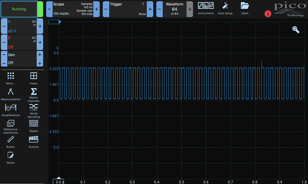
That seems to work. Now let’s check the clock speed and some data packets:
while(1) {
    bsp_spi1_cs_low();
    bsp_spi1_transfer(0xAA); // 0b10101010
    bsp_spi1_transfer(0xAF); // 0b10101111
    bsp_spi1_cs_high();

    for (volatile uint32_t i = 0; i < 100000; i++); //bit of a pause to make it easier to spot
}
I’ve used Picoscope 7 which has some nice logic analyser features built in, they have a specific setting for SPI - SDIO which only needs the clock and MOSI line (perfect as I only have 2 channels on my scope):
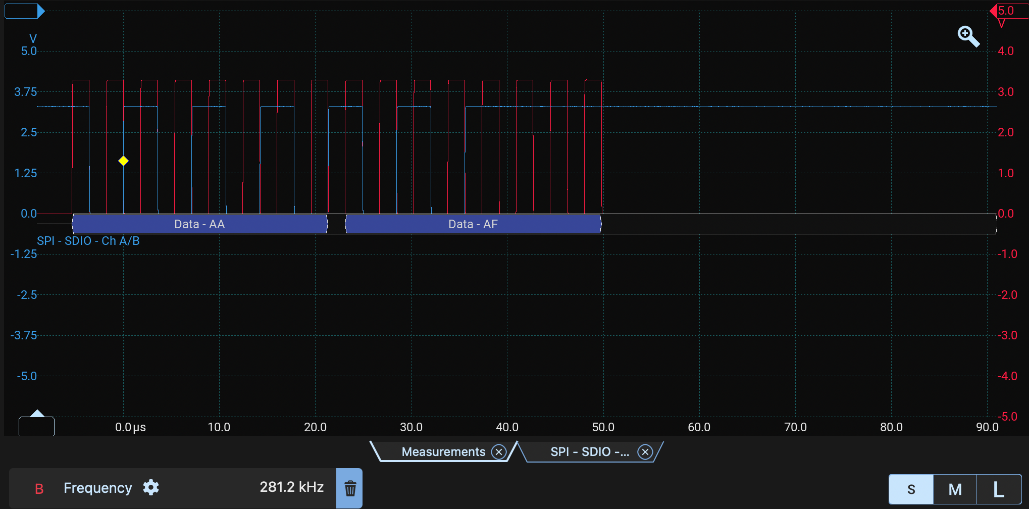
You can see the clock frequency measured is bang on 281.2 kHz on the red trace (B) and both data packets are there on the blue trace (A) too!
Next?
Now I have a small SPI1 board support package that can:
- Initialise SPI1
- Control chip select manually
- Send and receive bytes
- Read and write buffers
- Start slow and switch faster later
The next step is to write the SD card driver! That driver will send SD commands such as CMD0, CMD8 and ACMD41, move the card into SPI mode, and eventually provide the 512-byte block read/write functions that FatFS expects.
Copyright © 2026 David O’Connor