STM32 #10: microSD Storage on STM32F1xx: FAT(fs), SPI, and the Hardware Setup
This post will document some of the ground work for understanding how to connect and use a microSD in a simple manner with the STM32F103x but will leave full implementation until a later post.
Why add local storage
I have built a small device that is streaming I2C sensor data over UART(USB) to a custom logging web GUI. I now want to make the device wearable and so two initial phases come to mind; Making it battery powered, and giving it local storage for the sensor data logs.
SD Card Storage on the STM32F1xx
For this project, the easiest way to add removable local storage is probaly via microSD card over SPIm with FatFS provding the filesystem layer. FatFS was developed by ChaN. If using as FAT12, FAT16, or FAT32 the license is very similar to a BSD style. If using the exFAT implementation then a license via microsoft may be required. Sticking with FAT32 should be acceptable (giving an upper limit of 2TB (512bytes/sector) on the SDCard volume size, and maximum OS compatability) for most embedded applications.
Ways to organise memory for embedded
Here is a quick orientation on some of the options when adding memory media management to an embedded project. This is not a complete filesystem comparison, but it was enough to orient my own decision making:
| File System | Safety Type | Corruption Risk | Unwritten Data Retention | SD Physical Wear | Boot Recovery Speed | Native Compatability | Commercial Licensing |
|---|---|---|---|---|---|---|---|
| FAT32 (FatFs) | None | High | Loses last unclosed file | Low to medium | Fast | PC, Mac, Linux | 1-Clause BSD |
| exFAT (FatFs) | None | High | Loses last unclosed file | Low to medium | Fast | PC, Mac, Linux | Microsoft Licensing |
| LittleFs | Copy-on-write | Low | Loses data from uncommited write cycle | Low | Instant | All with tools | BSD-3-Clause or Apache 2.0 |
| Ext4 (lwext4) | Metadata Journal | Low | Loses data from uncommited write cycle | High | Medium | Linux, others with tools | BSD-3-Clause and GPLv2 |
| UDF | VATs | Low | Loses data from uncommited write cycle | Low | Instant | PC, Mac, Linux | Open, royalty-free ISO standard |
| Writing Raw Blocks | Up to you | Up to you | Loses data from MCU RAM | Low | Instant (Direct Pointer) | None | Your own |
There is also SPIFFS but apprently it is not appropriate for SD Cards due to wear.
From the table above there are several interesting options with LittleFS and UDF being the most interesting, but with FAT32 being the lowest barrier to access with FatFS being readily available, and the easiest royalty free system to develop with. In the future I may try LittleFS.
Introduction to FatFS and the FAT filesystem on a microSD
Firstly, a microSD card has no understanding of files and folders. It is essentially just a large array of storage blocks that are numbered. FatFS is a software layer that gives structure to the memory blocks.
FatFS is fairly easy to use e.g:
f_open(&file, "data.txt", FA_WRITE | FA_CREATE_ALWAYS);
f_write(&file, buffer, bytes, &bw);
f_close(&file);
Underneath that API, FatFS is managing sectors, clusters, directories, and volumes.
Sectors
For SDHC cards, the logical block length is fixed at 512 bytes. That maps cleanly onto FatFS, because the low-level disk interface reads and writes numbered 512-byte sectors.
So the SD card will be organised at the lowest level into sector 0, sector 1, sector 2 etc. When FatFS wants to read a file, behind the api FatFS will be running:
disk_read(pdrv, buffer, sector_number, sector_count);
for example it might read 1 sector starting at sector 2048 which means read 512 bytes from sector 2048.
The SD card just knows these numbered sectors/blocks.
Clusters
A group of one or more sectors. FatFS allocates storage in clusters, for example a cluster might equal 8 sectors = 8 x 512 bytes = 4096 bytes.
A file will typically occupy multiple clusters, these might be contiguous or fragmented in the cluster order. The File Allocation Table (FAT) records which cluster comes next e.g. cluster 14 -> cluster 64. Cluster 64 -> 872. The table tells the file system how data is linked together.
Directories
This is just a special file that contrains a list of file entries e.g. LOG.TXT, SENSOR.TXT, CONFIG.TXT. The directories are used when you run f_open or f_close to look up the file name entry which tells FatFS where the first file cluster is and the file size. Then FatFS uses the FAT table to follow the linked clusters.
Volumes
A volume is just the formatted filesystem area so generally you would see a microSD card setup as one FAT volume. You could have multiple volumes on the card but for our embedded application it is easier to use one volume with folders such as 0:/config/ 0:/calibrations/ 0:/updates 0:/logs/ 0:/data/
Basic layout of a FAT-formatted microSD card
I won’t go into too much detail here but you typically have these main areas:
- Boot sector / BPB (Contains information about the filesystem layout)
- FAT table 1
- FAT table 2, optional copy
- Root directory
- Data area (file and directory clusters)
A note on cluster size
The set cluster size will define the minimum amount of memory taken up by a file. For example if you have a file which contains 1KB of data but the minimum cluster size is 32KB then the file will be 32KB in size with a wasted 31 KB. So if lots of files are logged per data this could accumulate into significant amounts of memory very quickly! Therefore ingeneral for this application fewer files which are larger in size is going to be more efficinent unless we start controlling each file size.
For SDHC, one sector is 512 bytes, so the cluster size is normally set as a number of sectors per cluster:
1 sector per cluster = 512 bytes 8 sectors per cluster = 4 KB 32 sectors per cluster = 16 KB 64 sectors per cluster = 32 KB
You can’t just make the cluster size equal to 1 sector in all cases, there are obviously drawbacks to that. The FAT table must store one entry for every cluster and so for a 100 MB file using 512 byte clusters that would result in 204,800 FAT entries which is 819,200 bytes in comparison to 32 KB clusters which would result in 3200 FAT entries which is 12800 bytes. So tiny clusters make the FAT table much larger and makes FatFS do more work when following or extending a file. Furthermore the actual hardware implementation of the SD memory may be working at much larger memory sizes to erase data.
Essentially tiny clusters are only good when you have lots of tiny files to write such as config files, tiny text logs, tiny marker files, tiny calibration files and you are very tight on space. Larger clusters are going to be good when you have larger files that require sequential writes such as bigger data logging files from sensor capture.
File Names
Short File Name (SFN) vs Long File Name (LFN): SFNs use the DOS 8.3 style which is up to 8 characters for the name, a period, and up to 3 charaters for the extension, and stored as upper-case (Although itis case insensitive in the FatFS implementation) e.g. SENSOR01.TXT. LFNs allow up to 255 characters and retain mixed case lettering and spaces, this must be explicitly enabled in FatFS.
Why use SFNs:
-
Exach directory entry requires exactly 32 bytes of disk space giving it minimal memory footprint
-
This also requires minimal RAM usage of 32 bytes, compared to an LFN using up to 512 bytes, which is a concern as the STM32F103 only has 20KB.
-
It makes it faster to open, read, and write, because the directory search requires less bytes
-
Universal compatibility across all FAT systems.
Considering the intial files be logged will be time series data over days and months a format such as YYMMDDxx.csv is likely most appropriate for now. The “xx” may be used to denote a sequence of log files in a day, or if I decide to separate data out into filesand I stay safe by sticking to 0-9 and A-Z for the “xx” then we have 10 numbers + 26 letters which gives 36 options per character, since we have two characters we have 36 x 36 = 1296 unique possibilities, keeping upper case only to remove any issues with string searches in C which are case sensitive, whereas FatFS is case insensitive.
If you really want to optimise the RAM usage then setting the filenames in hexidecimal in your code will slightly optimise the C code and still give you 16 x 16 = 256 unique filenames per day, but makes them a pain to read manually without a post-hoc conversion.
Alternatively you can use a small amount of extra space by designating the files into directories that are 8.3 compliant for much more organisation. e.g. 0:/DATA/PPG/250101XX.CSV - This still uses less RAM than enabling the LFN, and if more than 1 file lands in each directory then you’ve saved memory foot print too as the directory is only logged once in the FAT.
That was way too much on filenames.
Connecting a microSD to STM32F1xx via SPI
microSD supports the SPI bus protocol natively. By default they operate in a native 4-bit SD mode, but can be forced into SPI mode with an initialisation command. This means you can directly wire the stm32f103x to the microSD card and it should work, as long as it is operating at 3.3v. There are published “simplified” standards that are freely available for standard (SD upto 2GB) and high capacity (SDHC upto 32GB) SD memory cards which includes the bus protocol and pinouts, along with a whole heap of the functionality. I’m not covering SDXC up to 2TB but it is backwards compatible to an extent with SD and SDHC protocols, there is also SDUC - up to 128TB…. Most importantly the SDHC standard uses a FAT32 file system which we will focus upon, if using cards smaller than 2GB it will be the SD standard which uses FAT 12, and FAT 16.
Some specifications for the SDHC standard
- Operating voltage: 2.7 - 3.6 V
- Default mode: 12.6 MB/sec (Clock 0-25 MHz)
- High-speed mode: 25 MB/sec (Clock 0-50 MHZ)
- Password protection
- 9 pins: clock, command, 3 power, and 4 data
The pinouts for SD cards are available in the simplified standards, but not for microSD, this appears to be in an addendum I cannot find, maybe it is behind the SD association paywall. Maybe I have missed something but the pinouts were frustratingly difficult to find from an official source, even microSD card datasheets don’t seem to have it, so I ended up going onto mouser, searching up microSD connectors and looking at the datasheets, here is the pinout:
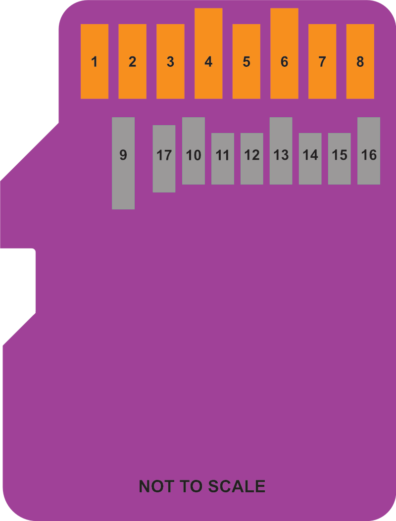
| Pin | Micro SD & Express Mode | SPI Mode |
|---|---|---|
| 1 | Data Line [Bit 2] | N/a |
| 2 | Card detect / Data line [Bit 3] | Chip Select |
| 3 | Command / Response | COPI (MOSI) |
| 4 | Supply voltage (3.3v) | Supply voltage (3.3v) |
| 5 | Clock | SCLK |
| 6 | Supply voltage ground | Supply voltage ground |
| 7 | Data Line [Bit 0] / RCLK + | CIPO (MISO) |
| 8 | Data Line [Bit 1] / RCLK - | N/a |
| Below are only for UHS-II | ||
| 9 | Supply voltage (1.8v) | |
| 10 | Supply voltage ground | |
| 11 | UHS-II D0+ | |
| 12 | UHS-II D0- | |
| 13 | Supply voltage ground | |
| 14 | UHS-II D1- | |
| 15 | UHS-II D1+ | |
| 16 | Supply voltage ground | |
| 17 | Single Wire Protocol Interface |
I added the UHS-II pins because they were there and I thought it may save me effort finding it again later!
So with that you could directly solder to a microSD connector and be away with SPI, or more reasonably you might have a custom PCB with a microSD connector, or you might have a breakout board such as the Adafruit microSD to SPI and SPIO
So I have connected the following pins, I’ve included the adafruit breakout but have not tried it:
| STM32F1xx | microSD Pin | Adafruit Breakout |
|---|---|---|
| 3.3v | Pin 4 V Supply | 3V Supply |
| GND | Pin 6 GND | GND |
| PA4 (GPIO CS) | Pin 2 CS | CS |
| PA5 (SPI1_SCK) | Pin 5 SCLK | SCK / CLK |
| PA6 (SPI1_MISO) | Pin 7 CIPO | MISO / DO |
| PA7 (SPI1_MOSI) | Pin 3 COPI | MOSI / DI |
Here is the abomination, it took me two tries until I switch from lead-free to the good stuff:
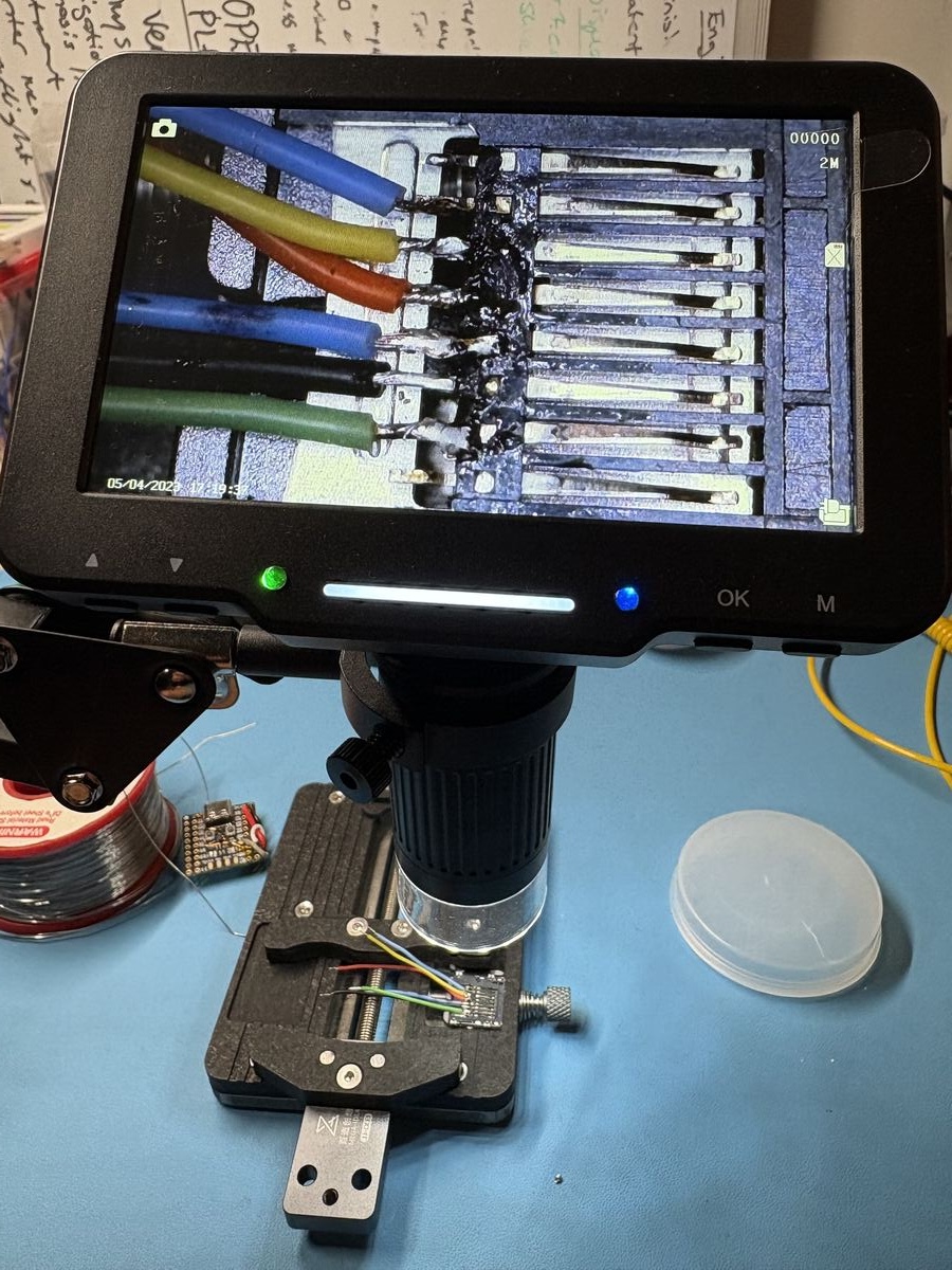
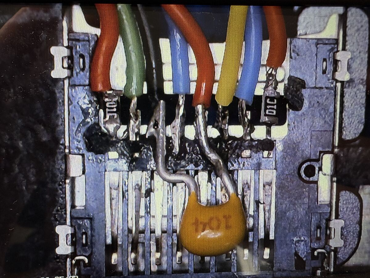
I have also added 0603 10kOhm pull ups between 3.3v and CMD, MOSI, MISO, and DAT1, DAT2 lines (for piece of mind incase there are issues with floating pins) and a 100nF(close to the microSD), and 10uF cap between V supply and GND to smooth out any noise and provide a reserve for current spikes at startup… Just use a dedicated breakout board unless you need the space savings!
microSD SPI Mode Introduction
We don’t need to cover too much of the protocol as FatFS will handle that but here are some key points that are good to know:
- SPI mode can be selected during the first reset command after a power cycle (CMD0) and cannot be changed once powered on.
- SPI mode is slower than standard SD mode due to using a single data line but makes the implementation fairly straight forward.
- SPI mode uses a subset of commands and functions from the SD mode before version 2.00 of the standard, and it does not work for SDUC cards.
- Every data token must be aligned with 8 clock cycles as a byte along with the CS signal.
- The host starts a bus transaction by pulling the CS pin low.
- If an error occurs with data retrieval the card will return an error response rather than the expected data block.
- For SDHC the data block length is fixed to 512 bytes, so partial read/write operations are not possible.
- Write protected commands are not available (CMD28, CMD29, CMD30)
What next?
Next I will write a SPI driver using libopencm3 for the STM32F103xx so that I can communicate with the card. After that I will develop the FatFs implementation to start storing the sensor data
Copyright © 2026 David O’Connor