STM32 #8: Binary, Bitwise Operators, Flags, and Register Control in Embedded C
For embedded C, bitwise operators are the key to understanding how to interact with communications protocols, data packets, and registers. I’ll start with a review of binary, then cover the bit wise operators, and move on to some applications for the STM32F1 bluepill.
A whistle stop tour through binary
The binary system is base two, and so each value can only be stored as two digits; a 1, or a 0. Much like the decimal system (base 10) where there are 10 digits 0-9, to give meaning above the digit 9, a representative meaning is given to the order of the digits. Binary is used because of how information is stored in hardware, it is much easier to store a 1 or 0 than venturing into trits, dits, or even qbits and beyond. So, to count to higher numbers than one, multiple binary digits are combined and given a representative value based on the digits order in a list. To convert to decimal, you take all the positions (n) given a 1 and sum their corresponding 2n values. For example, an unsigned 8 bit binary storage list will typically have the attributed values of: 27, 26, 25, 24, 23, 22, 21, & 20 to each corresponding bit. To represent the unsigned integer decimal 3 in 8 bits you would set the 20 + 21 positions to a 1 and the rest by 0s resulting in a binary representation of 00000011:
Binary position decimal meaning:    2**7       2**6       2**5       2**4       2**3       2**2       2**1       2**0
Binary representation of decimal 3: 0          0          0          0          0          0          1          1
Converting binary to decimal:       0*(2**7) + 0*(2**6) + 0*(2**5) + 0*(2**4) + 0*(2**3) + 0*(2**2) + 1*(2**1) + 1*(2**0) = 3
Are you a big-endian or a little-endian?
Wait waittt…. I don’t want to know, reality doesn’t exist until you measure it right, Schrodingers cat and all. Endianness is arbitrary. For this post big-endianness is assumed; The most significant bit is first, so for a 8 bit unsigned integer that would be the 27 bit, and the 20 bit is last. For example, the decimal number 3 in big-endian 8 bit unsigned binary is 00000011, which can also be specified using the binary specifier 0b as 0b11 in C23 where the big-endian convention is assumed. Another example would be decimal 119 is equivalent to 01110111 in binary, have a go! Under this regime with 8 bits, the range of unsigned integers you can store will be from 0 to 255.
Signed integers
We’ve covered the “unsigned” integer, so what if you want to store both negative and positive numbers? You can use the Two’s compliment convention; where the most significant bit (the first one in big-endian convention) is used to denote if the integer is a positive or negative. This changes the amount of numbers than can be represented compared to an equivalent sized unsigned integer. See if you can work out the range of values if the most significant bit is used for the polarity and not for 27… Did you get -127 to 127?… Wrong, you didn’t read the wiki did you! That would be the One’s compliment convention.
In Two’s Compliment zero is represented only once. Negative numbers are formed by taking the bit compliment (flipping all the bits) of the positive number’s magnitude and then adding 1. For example, an 8 bit signed int decimal 6:
+6 = 00000110
-6 = Invert bits (11111001) and add 1 (11111010).
Positive numbers are padded with leading zeros, and negative numbers are padded with leading ones, known as sign extension.
This encoding allows an extra value representation to be squeezed into the negative side, bringing the range of represented values to: -128 to 127 for a signed 8 bit integer. Squeezing every int out of that binary space.
That was a bit less whistle stop and a bit more lunch break, sorry!
Bit wise operators
If you have come across logical operators before this will be fairly straight forward. Instead of the integer, the operand is each bit, and the bitwise operator will run sequentially on every bit that makes up the memory address / register / integer / ASCI character, whatever it is, it doesn’t care, it all boils down to binary. So here are the main bit wise operators with their corresponding truth tables and unsigned 8 bit decimal examples:
Bitwise AND: &
If both bits being compared are 1 then a 1 is produced, if not then produce a zero.
A   B   =  A&B
0   0   =   0
1   0   =   0
0   1   =   0
1   1   =   1
Example:
A   = 00000011 = 3 in decimal
B   = 00001001 = 9 in decimal
A&B = 00000001 = 1 in decimal
Bitwise OR: |
Logical inclusive OR operation on each pair of bits. If both bits are zero the result is 0, otherwise it is one:
A   B   =  A|B
0   0   =   0
1   0   =   1
0   1   =   1
1   1   =   1
Example:
A   = 00000011 = 3 in decimal
B   = 00001001 = 9 in decimal
A|B = 00001011 = 11 in decimal
Bitwise XOR: ^
Logical exclusive OR operation on each pair of bits. If both bits are zero, or both are 1 the result is 0, otherwise it is one:
A   B   =  A^B
0   0   =   0
1   0   =   1
0   1   =   1
1   1   =   0
Example:
A   = 00000011 = 3 in decimal
B   = 00001001 = 9 in decimal
A|B = 00001010 = 10 in decimal
Bitwise NOT: ~
Also known as the bitwise compliment which flips all the bits to the opposite value; A 1 becomes a 0, and a 0 becomes a 1.
A   =  ~A
0   =   1
1   =   0
Example:
  A = 00000011 = 3 in decimal
~ A = 11111100 = 252 in decimal
Notice the resultant decimal number is 255 (the max possible respresentation) - 3 = 252
Bitwise shift left: « n
Shift all bits left (increase) by n places, bits that shift past the bounds of the register are discarded
Example:
A      = 00000011 = 3 decimal
A << 1 = 00000110 = 6 decimal
A << 2 = 00001100 = 12 decimal
Each position the value is shifted to the left, the value doubles, or the value is multiplied by 2**n, as long as it does not exceed (overflow) the register max bit range. This requires less compute than a typical multiplication routine. Where the end bit, big or small, moves into the register a 0 is initialised in the now “empty” spot. There are exceptions for signed integers where the sign bit is preserved.
Bitwise shift right » n
Like the left shift but shift all bits right (decrease) by n places.
Example:
A      = 00000011 = 3 in decimal
A >> 1 = 00000001 = 1 in decimal
A >> 2 = 00000000 = 0 in decimal
Each position that the value is shifted to the right, the value halves.
Types of shifts:
Ends are always contentious! Above we described arithmetic shifting, where signed integers keep their sign bit when shifted right. The counterpart is the logical shift, used for unsigned integers, which always fills new bits with zeros regardless of sign.
In contrast, an arithmetic right shift on a signed number would preserve the sign bit:
A      = 11111000  (-8)
A >> 1 = 11111100  (-4)
There’s also the circular (or rotate) shift, where bits that fall off one end of the register are wrapped around to the other side. This is less common in standard C but widely used in embedded systems, cryptography, and signal processing.
Example of an 8-bit circular shift:
A      = 00000011  (3)
A >> 1 = 10000001  (rotated right)
A << 1 = 00000110  (regular logical left shift)
The rotation shown above is illustrative and C’s » and « operators do not rotate.
Registers
Now we know how bit shifts work, we can write a function in C that can represent the values at a memory address / register in binary, as this isn’t in the standard library. Start with the basic template:
#include <stdio.h>

int main (void) {
 return 0;
}
Write a function which will take an input register and print the bits, placing this above the main function. We start with a function that takes the register variable as an uint8_t from <stdint.h>, so an unsigned 8 bit integer type to keep the visualisation simple. Inside a for loop, for each bit in the register, from largest to smallist, we will right bit shift the register by that position to bring it to the least significant bit position, then & it with 1 (00000001) and print the result. If there is a 1 in the register at that position the result will be a decimal 1, if there is not a 1 the result will be a decimal 0. Then we print that result before iterating the loop for all 8 bits:
#include <stdint.h> // reveals the uint8_t data type for our 8 bit register

void printBinary(uint8_t aRegister) {
    for (int i = 7; i>=0; i--) {
        printf("%d", (aRegister >> i) & 1);
    }
    printf("\n");
}
Back in the main loop lets set a value and call the print binary function:
uint8_t aRegister = 54;
printBinary(aRegister);
If you gcc this file and then run a.out (by default) you should have the binary representation of 54 printed out in the terminal. Here is the full code:
#include <stdio.h>
#include <stdint.h> // reveals the uint8_t data type for our 8 bit register

void printBinary(uint8_t aRegister) {
    for (int i = 7; i>=0; i--) {
        printf("%d", (aRegister >> i) & 1);
    }
    printf("\n");
}
int main (void) {
    uint8_t aRegister = 54;
    printBinary(aRegister);

    return 0;
}
Result:
>>> 00110110
How might it be useful for embedded… flags
Now that we can print bits, let’s see how to use them. Flags are where bit-level logic becomes truly practical. You can take a 8 bit register and store 8 flags inside it to denote a configuration in a memory/bandwidth efficient manner for example. Here is an example of an 8 bit flag register with 8 flags in it:
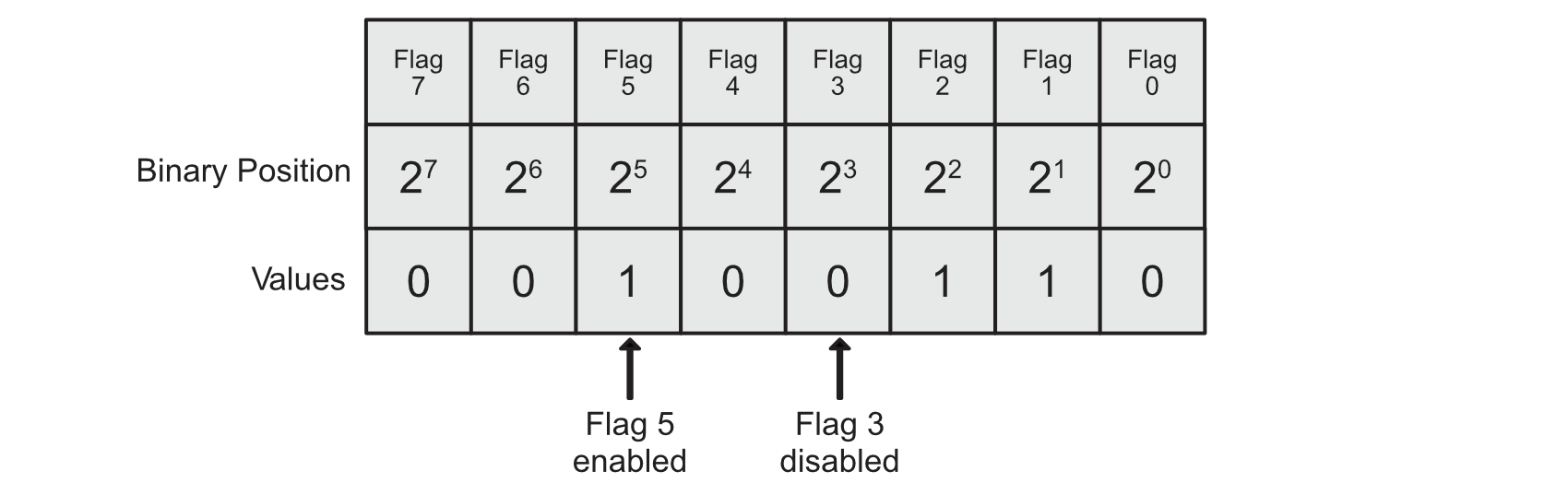
You can use the bitwise operators discussed to set and read flags stored in this much like the previous example. Lets say you have a 8 bit register holding the unsigned decimal value 2: 00000010. Now you want to find out if the 21 bit is a 1 or a 0. This one is simple, as all other bits are 0, so if you take another register that holds a single bit at the 21 bit and bit wise AND (&) it with the original register if both bits are 1, the result will also be 1, and a decimal value of 2 in this case:
flag_register                  = 00000010 = 2 in decimal
check_for_flag                 = 00000010 = 2 in decimal
flag_register & check_for_flag = 00000010 = 2 in decimal
Lets setup a basic C program to implement this, we will include the printBinary function we developed earlier for help visualising the binary, set a flags register to the decimal value 54, then check the first two least significant bits as the first and second flag and print if they are enabled or not:
#include <stdio.h>
#include <stdint.h>

void printBinary(uint8_t aRegister) {
    for (int i = 7; i>=0; i--) {
        printf("%d", (aRegister >> i) & 1);
    }
    printf("\n");
}

int main (void) {

    uint8_t flags = 54; // binary: 00110110
    printf("Flags: ");
    printBinary(flags);

    if ((flags & 1) !=0) {
        printf("Flag 1 - enabled\n");
    }
    else if ((flags & 1) == 0) {
        printf("Flag 1 - disabled\n");
    }
    if ((flags & 2) != 0) {
        printf("Flag 2 - enabled\n");
    }
    else if ((flags & 2) == 0) {
        printf("Flag 2 - disabled\n");
    }

    return 0;
}
Now this works because decimal 2 is 00000010 in binary, and decimal 1 is 00000001 in binary. So when we bitwise & these with the flag register they will only check for those positions. If you try this with the value 3 however, you will notice that it will now bitwise & successfully both 1 and 2, resulting in a decimal value of three. So this approach doesn’t quite scale for checking all of the bits independently. Lets write a checker which can scale a bit better (…sorry) and put it in its own function above main. We will do this by utilising the same method as the printBinary function; by right shifting the register so that the bit we want to check is shifted to the lest significant bit position and compared against a decimal 1 (0000001) with a bitwise &, if the bit being check is a 1 then the result is 1, otherwise it is 0:
void checkFlag(int bit, uint8_t flagRegister) {
    if ((flagRegister >> bit & 1) == 0) {
        printf("Flag: %i - disabled\n", bit);
    }
    else {
        printf("Flag: %i - enabled\n", bit);
    }
}
Then modify main to call that function for each flag you want to read, lets assume the flags register has 8 flags, one for each bit in the uint8_t sized memory address:
int main (void) {

    uint8_t flags = 54; // 00110110
    printf("Flags: ");
    printBinary(flags);

    for (int i=0; i<sizeof(flags)*8; i++) {
        checkFlag(i, flags);
    }
    return 0;
}
I used sizeof() here to introduce it, it will return the size of the memory in bytes, so 1 in this case, which I multiplied by 8 to get the number of bits.
The result should look like this:
Flags: 00110110
Flag: 0 - disabled
Flag: 1 - enabled
Flag: 2 - enabled
Flag: 3 - disabled
Flag: 4 - enabled
Flag: 5 - enabled
Flag: 6 - disabled
Flag: 7 - disabled
Here is the full code:
#include <stdio.h>
#include <stdint.h>

void printBinary(uint8_t aRegister) {
    for (int i = 7; i>=0; i--) {
        printf("%d", (aRegister >> i) & 1);
    }
    printf("\n");
}

void checkFlag(int bit, uint8_t flagRegister) {
    if ((flagRegister >> bit & 1) == 0) {
        printf("Flag: %i - disabled\n", bit);
    }
    else {
        printf("Flag: %i - enabled\n", bit);
    }
}

int main (void) {

    uint8_t flags = 54; // 00110110
    printf("Flags: ");
    printBinary(flags);

    for (int i=0; i<sizeof(flags)*8; i++) {
        checkFlag(i, flags);
    }
    return 0;
}
Enabling Flags
Using the bit wise OR operator you can statrt enabling things like flags in a register, and for this section rather than using the decimal values we will use direct binary represention using the 0b prefix (Only supported in C23 and greater), so the decimal value 2 = 0b10, 3 = 0b11, 4 = 0b100, etc. If you are using <C23 then you have to momentarily jump ahead and convert this to hex representation.
To set flag 0 from 0 to 1, without impacting the other flag bits, we simply bitwise OR it with 0b1, add this to the end of the main loop:
    printf("\nEnabling flag 0...\n");
    flags = flags | 0b1;

    printf("Flags: ");
    printBinary(flags);
    for (int i=0; i<sizeof(flags)*8; i++) {
        checkFlag(i, flags);
    }
The result is now
Enabling flag 0...
Flags: 00110111
Flag: 0 - enabled
Flag: 1 - enabled
Flag: 2 - enabled
Flag: 3 - disabled
Flag: 4 - enabled
Flag: 5 - enabled
Flag: 6 - disabled
Flag: 7 - disabled
With this type of set statement we can compound the bitwise OR to set multiple flags in one line if we so wish, setting flags = flags | 0b1 | 0b1000 | 0b1000000; for example should now result in a new flag register of 01111111, give it a try!
Resetting bits (Disabling flags)
What if you want to disable a flag? Lets take the 0b1000 flag at position 23 bit.
flags = 0b01111111;
flag3 = 0b00001000;
Rather than bit wise OR these two together to enable the bit, we can NOT flag3 to flip all the bits: ~flag3 which will result in 11110111, and then bit wise & that with the flags register. The result if the flag 3 bit was enabled - it will now be set to 0. Additionally, all other bits will be left unchanged. Here is the code, have a go:
    printf("\nDisabling flag 3...\n");
    flags = flags & ~0b1000;

    printf("Flags: ");
    printBinary(flags);
    for (int i=0; i<sizeof(flags)*8; i++) {
        checkFlag(i, flags);
    }
This can also be compounded to disable multiple flags at the same time.
Macros
Trying to remember the binary for each flag gets a bit tough and is not very readable, so we can modify the code to use macros for each flag which makes the whole procedure much easier to read now we understand what is happening under the hood. Here is the final code utilising macros, implemented in C23: (If you are using <C23 then you will have to convert the binary representation to hex)
#include <stdio.h>
#include <stdint.h>

#define FLAG_0 0b00000001
#define FLAG_1 0b00000010
#define FLAG_2 0b00000100
#define FLAG_3 0b00001000
#define FLAG_4 0b00010000
#define FLAG_5 0b00100000
#define FLAG_6 0b01000000
#define FLAG_7 0b10000000

void printBinary(uint8_t aRegister) {
    for (int i = 7; i>=0; i--) {
        printf("%d", (aRegister >> i) & 1);
    }
    printf("\n");
}

void checkFlag(int bit, uint8_t flagRegister) {
    if ((flagRegister >> bit & 1) == 0) {
        printf("Flag: %i - disabled\n", bit);
    }
    else {
        printf("Flag: %i - enabled\n", bit);
    }
}

int main (void) {

    uint8_t flags = 54; // 00110110

    printf("Flags: ");
    printBinary(flags);
    for (int i=0; i<sizeof(flags)*8; i++) {
        checkFlag(i, flags);
    }

    // Enable FLAG_0
    printf("\nEnabling flag 0...\n");
    flags = flags | FLAG_0;

    printf("Flags: ");
    printBinary(flags);
    for (int i=0; i<sizeof(flags)*8; i++) {
        checkFlag(i, flags);
    }

    // Disable FLAG_3
    printf("\nDisabling flag 3...\n");
    flags = flags & ~FLAG_3;

    printf("Flags: ");
    printBinary(flags);
    for (int i=0; i<sizeof(flags)*8; i++) {
        checkFlag(i, flags);
    }

    return 0;
}
Now it’s starting to look like embedded, prepare to be vexed, hexed, and nibbled!
We’ve have blown a cannonball through many of the abstract layers, and you should now find yourself staring at bare metal.
If everything inside a microcontroller is binary, why don’t we just write binary literals directly using 0b like we did in the above macro definition… Enter the hexadecimal.
Hexadecimal is a base 16 representation as shown in the image below:
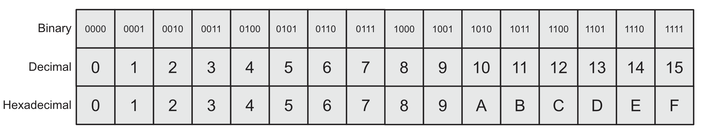
Base 16 allows values to be represented in a compact manner, for example if we wanted to set the decmial value: 40960 in binary that would be: 0b1010000000000000, but in hexadecimal it is 0xA000. There are a lot of zeros in that binary, it would be very easy to miss one out, causing all sorts of chaos leaving you vexed. As you might have guessed the 0x prepend tells C that the value is encoded in hexadecimal.
Each hex digit can be represented by 4 binary bits as seen in the image above, this is known as a nibble! (Half a byte). This makes it easy to convert between binary and hex, you just split the binary into nibbles and use the table above: 0xA000 = 1010 0000 0000 0000. A nibble aligns quite nicely with much in embedded such as 8, 16, 32 bit and so on registers. So a 32 bit register can be represented by 8 hexadecimal digits.
Hexadecimal is not so good for visualising bit masks so you will often see conversions but it is always used preferentially over the binary 0b representation due to it being the widely accepted convetion and much more long standing representation in the C language (since 1989) than the 0b specificer. It is typically the convention used in most datasheets and headers.
Lastly, on the point of expressing bit masks, in production code you would often avoid this all together by defining bits with macros and shifting them to where you want. For example defining a decimal 1 unsigned as we previously have, and then left shifting it to the position you want to create the bit mask for and assigning it to a #define. This example here for USART TX enable flag makes it bvery clear we are assigning bit 3 in the register:
#define USART_CR1_TE (1U << 3) // shifts decimal 1 left by 3 places = 0b1000 = 0x08
Now it’s actually starting to look like embedded…
In STM32, peripheral registers are memory-mapped. You read/write bits to configure hardware or check status flags. CMSIS gives you typed structs (e.g., GPIOA, USART2, RCC) so you can do clean and safe bit operations. Note that in the previous example we have used the pure C binary specifier 0bxx… however for embedded it is typically better to use hex as 0b can be compiler and implementaiton specific (brought in in C23). For hex representation 0x is used at the beginning and u at the end to denote unsigned, so a unsigned int 3 in hex is 0x3u.
For example, you can directly enable the GPIOA clock via modifying the APB2ENR register. Everything previous was pure C, below, these will have to be in a STM32 embedded project like the previous blog posts.
#include "stm32f1xx.h"

// Enable GPIOA clock by setting the GPIOAEN bit
RCC->AHB1ENR |= RCC_APB2ENR_IOPAEN;

// Check if it is set by reading the flag
if (RCC->APB2ENR & RCC_APB2ENR_IOPAEN) {
    // Do some stuff because the flag is enabled
}
You might want to configure a pin mode by masking a multi-bit field. Many fields are 2 bit slices such as the STM32F4 chips where each GPIO pin has a 2-bit mode register: GPIOx->MODER representing 00=input, 01=output, 10=AF, 11=analog. On the STM32F1 series there are 4 bits per pin: CNF[1:0] + MODE[1:0]. For example to configure PA5 as a general purpose push pull output @ 2MHz you must set MODE to 10, and CNF to 00 which can be done with the binary mask 0b0010 or in hex 0x2:
// Configure PA5 as general-purpose output
// Clear the 4-bit field for pin 5 (in CRL: pins 0–7)
GPIOA->CRL &= ~(0xFu << (5 * 4));

// Set MODE=10 (2 MHz), CNF=00 (GP push-pull) → 0x2 (0x3=50Mhz, 0x1=10MHz)
GPIOA->CRL |=  (0x2u << (5 * 4));
Mask then set is the safest pattern for multi-bit fields.
Bit Set/Reset Register (STM32F1x)
You can set and clear output bits automatically with the Bit Set/Reset Register (BSRR). Writing to GPIOx->BSRR avoids read-modify-write issue like race conditions and is atomic on Cortex-M. The GPIOx_BSRR register is a 32-bit write only register which is divided into two halves;
- Bits 0-15 are set bits, writing a 1 sets the corresponding output bit to 1 or HIGH.
- Bits 16-31 are reset bits, writing a 1 sets the corresponding output bit to 0 or LOW.
See RM0008 for more details on the BSRR. Here is an example of setting and resetting the PA5 pin on GPIOA:
// Set PA5 high
GPIOA->BSRR = (0x1u << 5);

// Set PA5 low (write to reset upper-half)
GPIOA->BSRR = (0x1u << (5 + 16));
Avoid using GPIOA->ODR |= ... in ISRs or multi-context code. BSRR is better for this. If using libopencm3, the BSRR is utilised by the gpio_set() and gpio_clear() functions making them atomic and safe to use. For example if you executed gpio_set(GPIOA, GPIO5) it would employ GPIO_BSRR = (0x1u << 5) to set bit 5 in the BSRR register. However with your knowledge of bitwise operators now you could do something like set a bunch of pins at the same time with the bit wise OR:
gpio_set(GPIOA, GPIO5 | GPIO6 | GPIO7); // sets PA5, PA6, and PA7
Those GPIOx constants are just bit masks like the FLAG_x masks from earlier.
More often though you might need to manipulate some of the less abstracted registers such as the Reset and Clock Control (RCC), External interrupts (EXTI), Alternate function remapping (AFIO), and the Interrup enable bits (NVIC).
USART Communication Example on the STM32F1xx
You could also do something like read a pin with the Input Data Register (IDR) or a status flag with the Status Regester (SR), Data Register (DR) and Transmit Data Register (TDR). We will bring this all together with a complete code example by trying to transmit a byte on USART2.
From the RM0008 manual the relevant registers are:
- USARTx->SR - Status Register
- USART_SR_TXE - Transmit data register empty. (bit 7)
- 1 means DR can accept a new byte.
- Cleared by writing to DR.
- USART_SR_TC - Transmission complete / stop bit sent (bit 6)
- USART_SR_TXE - Transmit data register empty. (bit 7)
- USARTx->DR - Data register
- Write a byte here to start data transmission when TXE=1
- Read from here when RXNE=1 to get the recieved byte
- USARTx->BRR - Baud Rate Register
- Holds the USART divider for the APB clock to set the baud rate.
- USARTx->CR1 - Control Register 1
- UE - USART Enable (bit 13)
- TE - Transmitter Enable (bit 3)
- RE - Reciever Enable (bit 2)
Also check out the CR2 and CR3 registers for stop bits and flow control.
Let’s start by setting up a blank tempalte for the STM32f1 chip (Bluepill C8T6):
#include "stm32f1xx.h"

int main (void) {
    for (;;) {
        // Do stuff
    }
}
Lets create a function to initialise USART. We will start with enabling the clocks:
static void usart2_init_115200(void) {
    // Clocks: GPIOA on APB2, USART2 on APB1

    // Enable the APB2 peripheral clock and direct it to GPIOA (IOPAEN), Turn on AFIO
    RCC->APB2ENR |= RCC_APB2ENR_IOPAEN | RCC_APB2ENR_AFIOEN;

    // Enable the APB1 peripheral clock and direct it to USART2
    RCC->APB1ENR |= RCC_APB1ENR_USART2EN;
}
If you want to change the USART2 pin mapping from PA2 and PA3 to PD5 and PD6, set the AFIO register to remap: AFIO->MAPR |= AFIO_MAPR_USART2_REMAP.
Next inside the usart2_init_115200() function we will configure the PA2 and PA3 pins for USART. Pins 0-7 are configured in the CRL register and pins 8-15 in CRH. Each pin has 4 bits 2 for configureation and 2 for mode: CNF[1:0], MODE[1:0].
For output mode:
- MODE: 01=10 MHz, 10=2 MHz, 11=50 MHz
- CNF: 00=GP push-pull, 01=GP open-drain, 10=AF push-pull, 11=AF open-drain
For input mode:
- MODE: 00=input
- CNF: 00=analog, 01=floating, 10=pull-up/pulldown, 11=reserved
Lets set the PA2 TX pin:
    // TX (PA2): Alternate function push pull, 50MHz
    // CNF=10, MODE=11, bit mask = 0b1011 = 0xB
    GPIOA->CRL &= ~(0xFu << (2 *4)); // reset the 4 bit field
    GPIOA->CRL |= (0xBu << (2 * 4)); // write 1011
Now the PA3 RX pin:
    // RX (PA3): Input floating
    // CNF=01, MODE=00, bit mask = 0b0100 = 0x4
    GPIOA->CRL &= ~(0xFu << (3 * 4));
    GPIOA->CRL |= (0x4u << (3 * 4));
We must configure the Baud rate. Make sure your PCLK1 is running at 36 MHz: SYSCLK=72 MHZ, APB1 prescaler=2 which results in 36 MHz. If APB1 is at a different rate the you’ll have to modify the calculations I use below. Ripped from RM0008:
“The baud rate for the reciever and transmitter (Rx and Tx) are both set to the same value as programmed in the Mantissa and Fraction values of USARTDIV.”
The F1 chip also oversamples by 16, the baud-rate generator counts 16 peripheral clocks for each bit period. And so you will see the denominator has a 16x multiplier for the oversampling:
Tx/Rx baud = fPCLK / (16*USARTDIV)

fPCLK: Input clock to the peripheral (PCLK1 for USART 2,3,4,5, PCLK2 for USART1)
USARTDIV: Unsigned fixed point number coded on the USART_BRR register.
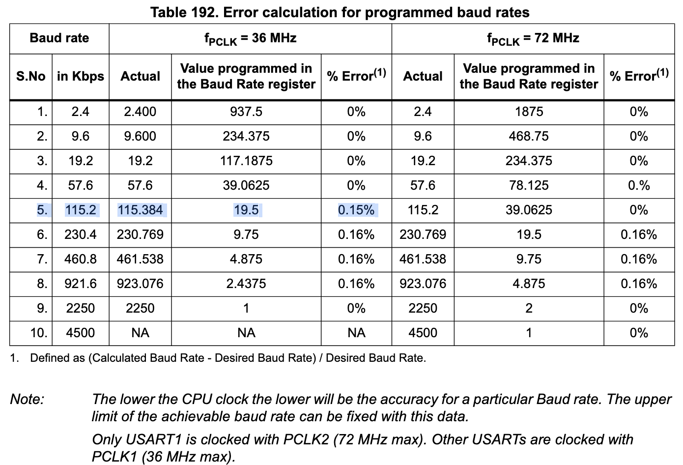
However it isn’t quite that simple. If we set the baud rate to 115200, with the PCLK1 at 36 MHz. BRR = fPCLK / 16baud = 36,000,000 / (16115,200) = 19.53125. However, recalling the statement from RM0008 above the BRR is based on the mantissa (part of a floating point number representing the significant digits) and fraction values (as ints). So the number must be rounded to fit nicely into the registers. The following table from RM0008 suggests 19.5:
For the USART_BRR register, the USARTDIV is split into:
- USART_BRR[15:4] is the mantissa (12 bits)
- USART_BRR[3:0] is the fraction (4 bits) - with the fraction being divided by 16 due to the over sampling. Each increment of the low nibble adds 1/16 to the USARTDIV.
Conceptually this makes USARTDIV = mantissa + fraction/16
So to fit 19.53125 nicely into the BRR register we can chose 19 + 8/16 or 19 + 9/16. The table has shown 19.5 with the error values so lets go with that and round down, rounding up to 9/16 would produce the same error.
So to get the values into the BRR register we have:
BRR = (mantissa << 4) | (fraction & 0xF)
BRR = (0x13 << 4) | 0x8 = 0x1388
So lets add that to the init function:
    // Set baud 115200,
    USART2->BRR = 0x1388;
On a side note if PCLK1 = 72 MHz you’ll notice in the table that at 115200 baud is exactly 39 + 1/16 producing 0% error.
Now we can enable the USART, and the TX and RX!
USART2->CR1 |= USART_CR1_UE | USART_CR1_TE | USART_CR1_RE;
If word length, partity and stop btis need to be changed ser CR1 and CR2 accordingly before setting UE. Now we are done with our initiliase funciton.
Lets produce a small function to write bytes to USART2:
static void usart2_write_byte(uint8_t b) {
    // Wait for TXE=1
    while ((USART2->SR & USART_SR_TXE) == 0) {
        //spin
    }
    USART2->DR = b; // Writing DR clears TXE and starts shifting the byte b
}
Go back into the main function to tie everything up:
int main (void) {
    usart2_init_115200();

    usart2_write_byte('A'); // Send the char A
    while ((USART2->SR & USART_SR_TC) == 0) {
        // wait for TX complete
    }

    for (;;) {
        //do stuff
    }
}
Here is the full code:
static void usart2_init_115200(void) {
    // Clocks: GPIOA on APB2, USART2 on APB1

    // Enable the APB2 peripheral clock and direct it to GPIOA (IOPAEN), Turn on AFIO
    RCC->APB2ENR |= RCC_APB2ENR_IOPAEN | RCC_APB2ENR_AFIOEN;

    // Enable the APB1 peripheral clock and direct it to USART2
    RCC->APB1ENR |= RCC_APB1ENR_USART2EN;

    // TX (PA2): Alternate function push pull, 50MHz
    // CNF=10, MODE=11, bit mask = 0b1011 = 0xB
    GPIOA->CRL &= ~(0xFu << (2 *4)); // reset the 4 bit field
    GPIOA->CRL |= (0xBu << (2 * 4)); // write 1011

    // RX (PA3): Input floating
    // CNF=01, MODE=00, bit mask = 0b0100 = 0x4
    GPIOA->CRL &= ~(0xFu << (3 * 4));
    GPIOA->CRL |= (0x4u << (3 * 4));

    // Set baud 115200, PCLK = 36MHz
    USART2->BRR = 0x1388;

    // Enable USART, TX, RX
    USART2->CR1 |= USART_CR1_UE | USART_CR1_TE | USART_CR1_RE;
}


static void usart2_write_byte(uint8_t b) {
    // Wait for TXE=1
    while ((USART2->SR & USART_SR_TXE) == 0) {
        //spin
    }
    USART2->DR = b; // Writing DR clears TXE and starts shifting the byte b
}


int main (void) {
    usart2_init_115200();

    usart2_write_byte('A'); // Send the char A
    while ((USART2->SR & USART_SR_TC) == 0) {
        // wait for TX complete
    }

    for (;;) {
        //do stuff
    }
}
Lastly, avoid using pure C bit-fields (structs) for registers. They can break with implementation specific layouts, padding, and non-atomic practices. For hardware registers, masks and shifts are the robust and portable way to do it.
That is all.
Copyright © 2025 David O’Connor