STM32 #7: UART Communication on STM32F1xx with libopencm3
There are more ways than the ARM SWD debugger interface to communicate to the STM32. One of the earliest serial protocols; Universal asynchronous reciever / transmitter (UART) protocol can be used. On your device you will probably have come across UART via a Serial (COM) port on a PC, and also used in the mostly depreciated RS-232 protocol.
UART Protocol
UART requires, at minimum; a transmit line (TX) or recieve line (RX), and a reference ground (GND). The handling of data across these lines fits into three main catagories:
- Simplex: Data is sent in only one direction.
- Half-duplex: Data can be sent in either direction but not at the same time.
- Full-duplex: Data can be sent in both directions simultaniously.
Data is transmitted in “Frames” and is generally used for low data / low speed applications compared to newer protocols such as SPI or I2C.
UART is quite special as it is asynchronous, which greatly simplifies the protocol. The transmitter and reciever do not share a common clock source, but instead have a predetermined communication rate known as the “baud” rate ( 1 / time in seconds for 1 bit). Both sides of the comminiucation need to also have a predetermined message structre that matches.
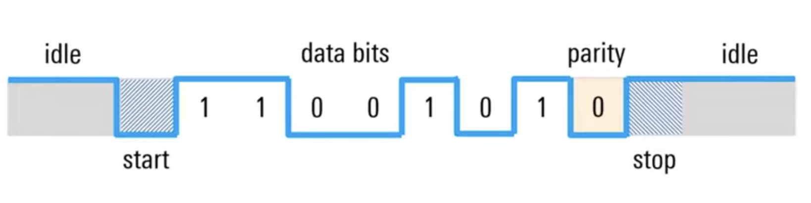
The TX/RX pin will be held at high-voltage (1 bit) (3.3 or 5v usually) when idling. Once a message is ready to be sent the high signal will be pulled to low-voltage (0 bit) (close to 0v)and is known as the start bit to signal to the RX on the other end that a message is incoming.
The frame bits will be sent in order of the least significant bit first. A simple example is a 1 byte message (8 bits) also known as a “char”, but could be from 5-9 depending on configuration. The end of the data transmission is signaled by a “stop bit” where the signal is pulled high. The stop bit can be set to different amounts such as 0.5, 1, 1.5, & 2 bits. The stop bit may need to be increased from 1 if the reciever needs more time between two message “frames” but it is often just 1 bit.
Additionally, as you will see in the picture (ripped from Rhode & Schwarz) a parity bit can be placed before the stop bit. The parity bit is a attempt to verify if the message that was sent has been recieved as intended and not corrupt by something such as noise. This is done by predetermining what the parity bit is signifying, it can signify if: - The sum of all 1 bits in the frame equal an even number - The sum of all 1 bits in the frame equal an odd number
The parity bit is calculated for each frame and sent with it. This allows the reciever to check the integrity of the message. If one bit gets flipped during the transmission; the sum of all 1s will not agree with the indication from the parity bit. However if an even number of bits are flipped, then the sum will agree with the parity bit and the reciever will be none the wiser so it is not fool proof, although there are more complicated ways to solve this problem.
UART TX with Bluepill, libopencm3 and nanoprintf
Before I begin here, to create a project from scratch you will need to understand the Makefile, someone else has done a much better job than I ever could at explaining the make file here
There are many ways you can start a project, but if you want to avoid writing your own makefile and linker, then you can also start with the empty project template that libopencm3 recommends on their github, for that, goin into a directory that you want your project directory to be in and run the following command to clone the template:
git clone --recurse-submodules https://github.com/libopencm3/libopencm3-template.git usart-tutorial
cd into usart-tutorial and you will find a nice template sorted for you, open the README.md for instructions on compiling your code, but before you do that, cd into my-project and open the Makefile in a text editor - Modify the PROJECT, DEVICE, and OOCD_FILE to match. This will ensure you are compiling the binaries for the correct board (CBT6 varient, otherwise for DEVICE put your device if it is different, such as STM32F103C8T6):
PROJECT = uart-tutorial
BUILD_DIR = bin

SHARED_DIR = ../my-common-code
CFILES = my-project.c
CFILES += api.c
AFILES += api-asm.S

# TODO - you will need to edit these two lines!
DEVICE=stm32f103cbt6
OOCD_FILE = board/stm32f1x.cfg

# You shouldn't have to edit anything below here.
VPATH += $(SHARED_DIR)
INCLUDES += $(patsubst %,-I%, . $(SHARED_DIR))
OPENCM3_DIR=../libopencm3

include $(OPENCM3_DIR)/mk/genlink-config.mk
include ../rules.mk
include $(OPENCM3_DIR)/mk/genlink-rules.mk
Now cd up a level and perform the two make commands. You are ready to start writing code!
Setup the UART module with Libopencm3
The STM32F1x has 3 UART Serial ports attached to PA_2 & PA_3, PB_6 & PB_7, PA_9 & PA_10, and PB_10 & PB_11:

Check the exact 5v tolerance per pin/mode in the STM32F103 datasheet; UART RX (as input) is generally fine with 5v tolerant pins, but don’t drive non-tolerant pins above VDD, the pin out I found here shows a 3.3v limit on Serial2 pins. Plug in the TX pin of your chosing on the bluepill, I will use USART1 at pins PA_9 & PA_10.
A summary of the pin assignments:
- USART1: TX PA9, RX PA10 (APB2)
- USART2: TX PA2, RX PA3 (APB1)
- USART3: TX PB10, RX PB11 (APB1)
Note: It is possible to remapped USART1 to PB6/7 via the alternate function pin selection (AFIO) module (libopencm3/stm32/afio.h) using gpio_primary_remap(AFIO_MAPR_SWJ_CFG_JTAG_OFF_SW_ON, AFIO_MPR_USART1_REMAP) - libopencm3 doc
Inside my-project create a header file for the uart module, uart.h:
First add an include guard, so that if you incude this header in multiple files (can happen automatically through other headers) it will avoid compiler errors. Include guards in embedded headers prevent chaos from the spaghetti of peripheral dependencies, big vendor libraries, and indirect includes:
#ifndef UART_H // if not defined, then define it!
#define UART_H // setting macro if already defined
Define some basic functions that we will build for sending data across UART:
void uart_init(void);
void uart_send_char(char c);
void uart_send_string(const char *str);

#endif // this ends the include guard!
Create the main uart module utilising libopencm3, uart.c:
Include the library headers:
#include <libopencm3/stm32/rcc.h>
#include <libopencm3/stm32/gpio.h>
#include <libopencm3/stm32/usart.h> // New library that we will use

#include "uart.h"
Create a function to initialise the UART configuration
void uart_init(void){
    // Initialise the uart port

    // Enable the peripheral clock that the USART1 IO pins are on.
    rcc_periph_clock_enable(RCC_GPIOA);

    // Enable the peripheral clock specifically for the USART port
    rcc_periph_clock_enable(RCC_USART1);

    // Set the chosen USART GPIO pins to work with UART, note the ALTFN_PUSHPULL, this is specifically for UART
    gpio_set_mode(GPIOA,
                  GPIO_MODE_OUTPUT_50_MHZ,
                  GPIO_CNF_OUTPUT_ALTFN_PUSHPULL,
                  GPIO9 // GPIO_USART1_TX
                  );

    // Initialise USART protocol configuration using libopencm3
    usart_set_baudrate(USART1, 9600);
    usart_set_databits(USART1, 8);
    usart_set_stopbits(USART1, USART_STOPBITS_1);
    usart_set_parity(USART1, USART_PARITY_NONE);
    usart_set_flow_control(USART1, USART_FLOWCONTROL_NONE);
    usart_set_mode(USART1, USART_MODE_TX); // A simple asynchronous transmit only mode.
    usart_enable(USART1);
}
Notice, that we have set the flow control to NONE, using the USART commands, so when using asynchronous (UART) you still use the synchronous (USART) functions to set this. In libopencm3 you will confusingly find both a USART and UART API… The UART API seems to be a simplified wrapper for a subset of the USART API. When consulting the STM31F1x RM0008 manual, the peripherals are USARTs (Universal Synchronous/Asynchronous). We’ll use them in asynchronous ‘UART’ mode.
Create two small wrapper functions to handle chars and strings. For this we will utilise the libopencm3 USART API again:
void uart_send_char(char c){
    // Sends a byte via USART1
    usart_send_blocking(USART1, c);
}

void uart_send_string(const char *str){
    // Sends each char (byte) one by one using the previous function
    while (*str) {
        uart_send_char(*str++);
    }
}
Create your main.c file and include the uart header:
#include "uart.h"
Write a small main loop to send some stuff over uart using the uart_send_String command we made:
int main(void) {
    uart_init();
    while(1){
        uart_send_string("UART TX works, wahooo!");
    }
}
Save that and go back into your Makefile to add the uart.c file so that the linker knows where to look, add this after line 6:
CFILES += uart.c
You are ready to flash! Run a make clean, then make command to make sure everything has compiled correctly.
Connect your device up via the ST-Link v2 SWD debugger. Run st-info –probe to check your device is connected. Then run st-flash write uart-project.bin 0x8000000 (or whatever the .bin file is called (based on your Makefile PROJECT variable).
No connect up a USART/UART to USB device, preferably an FTDI based one, connect the pins up to the correct enabled USART pins, in this case PA9 & PA10, although we only need the TX pin on the bluepill connected to the RX pin of the UART to USB board, and make sure the ground is connected. If you still have the bluepill powered via the connected ST-Link v2, then do not connect the power up from the UARt to USB device to the bulepill, follow the one power source rule!
run a grep to check for the uart to usb deivce:
ls /dev | grep -i usb
and you should be able to find the serial address.
Install minicom if you haven’t already, then run the following in the terminal to get a serial terminal running:
minicom -D /dev/{address of uart device from previous grep} -b 9600
This should connect to your UART to USB device and be listening to the bluepill output, if everything went well you’ll see the message being printed on one line:
“The UART works woohooo!The UART works wThe UART works woohooo!”
It’s all printing on one line, but it works! Okay lets move on to trying to make the output more readable and usable…
nanoprintf
nanoprintf is a tiny printf library with a reasonably good feature set aimed at embedded devices. This is all packaged into a single drop in file that does not rely on libc and is released with a 0BSD license, which is unconditional and so can be used very freely.
There are 4 main APIs:
- npf_snprintf: For use like snprintf from the stanadrd C library.
- “Loads the data from the given locations, converts them to character string equivalents and writes the results to a variety of sinks/streams”
- snprintf is a safe version of sprintf(), which is used to format strings into a buffer. This version prevents buffer overflows, and guarantees the string is null terminated.
-
npf_vsnprintf: For use like vsnprintf from the standard C library
- npf_pprintf: For use like printf with per-character write callback.
- This would be used when you do not want to write to a buffer like npf_snprintf but instead to format and send each char immediately, which is great for low-memory systems (Like for UART comms on the STM32F1!)
- npf_vpprintf: For use like npf_pprintf but it takes a va_list
For further details checkout nanoprintf on charles nicholson’s github.
Here are some basic formatting speficiers you can use:
- %s string
- %d or %i for signed integer
- %u for unsigned integer
- %x or %X for hex
- %c for char
- %f for float (configuration dependent)
Once you have “git submodule add”-ed the nanoprintf repo to the my-project directory we will start to integrate it.
In main.c add the two lines to link to the nanoprint header file:
#define NANOPRINTF_IMPLEMENTATION
#include "./nanoprintf/nanoprintf.h" // path to nanprint header file
First we need to understand a bit more about the typical ways things are printed in standard C. There are three main methods:
- putchar(int c): Writes one character to stdout
- puts(const char *s): Writes a C string to stdout, and adds \n
- printf(const char *fmt, …): Does formatting and writes the result to stdout.
With embedded there is often not a stdout, so nanoprintf and other small print libraries do not depend on stdout. Instead you must provide a callback they can call for each character. So we must build a custom putc function and then feed the address to that function into nanoprints printf style function.
It might seem counter intuative at first but a putcfunction conventionally takes an int rather than a char for it’s argument type. There are two reasons I can find for using an int:
- It needs extra space for an EOF character (-1) which would not fit in the address space of a char.
- In C if you pass a char to a function expecting an int, it is automatically promoted to an int. So convention here winds, due to the argument requirements of nanoprintf. Lastly, the argument of uart_send_char need to be cast back to a char! This stops anything from overflowing… I think.
void uart_putc(int c, void *ud) {
    // Custom putc function
    (void)ud;
    uart_send_char((char)c);
}
Make sure to add the uart_putc prototype at the top of the file.
Make a custom function that feeds the uart_putc into npf_pprintf() from nanoprint:
void print_to_uart(char *message, int count){
    npf_pprintf(&uart_putc, NULL, "\rMsg: %s %i", message, count);
}
(don’t forget the prototype!)
Now write the main function to iterate a counter, print the message and then wait for a bit in a horrible blocking manner, just so you can see the changes at a reasonable speed:
int count = 0;

int main(void) {
    uart_init();
    char message[] = "Wohoo UART works!";

    while(1){

        print_to_uart(message, count);
        ++count;
        for (volatile uint32_t i=0; i<800000; i++){
            __asm__("nop");
        }
    }
}
Run make, then st-flash and you can fire up minicom again and see the result!
Copyright © 2025 David O’Connor