STM32 #3: From Template to Blinky - Building Bluepill Firmware with libopencm3
Board: WeActStudio BluePill Plus STM32 F103CBT8 (Arm Coretex M3)
The Nucleo board is outdated and quite bulky. A more popular alternative would be the Bluepill (and Blackpill) development boards, which can be picked up for next to nothing on aliexpress. They became popular becasue there was a variation that could be utlilise the Arduino IDE in arduino style code which made them very accessible. I will be trying to get slightly closer to the hardware by using libopencm3 rather than STM32 HAL, and so picked myself up a slightly modernised WeActStudio Bluepill Plus with a STM32F103CBT6 micro. It is very similar to the nucleo board but more powerful, smaller, cheaper, and more widely used. It is probably a counterfit/used chip considering the whole dev board was £2.09!
Here is a link to the SoC specs/documentation on the ST Site. It has a Cortex M3 processor rather than the Cortex M0 of the Nucleo board we used before. The common Bluepill comes with a chip ending in C8T6, where as I have the CBT6 version which comes with additional 64 MB of flash memory. Lastly, I managed to get a version with USB-C. Following along with a Bluepill or Bluepill Plus will be almost identicle, just keep an eye on the pinouts.
Here is a link to the ST Reference manual for the chip series: RM0008
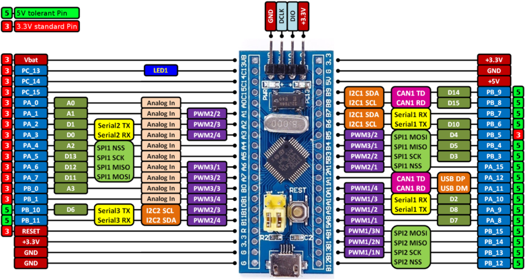
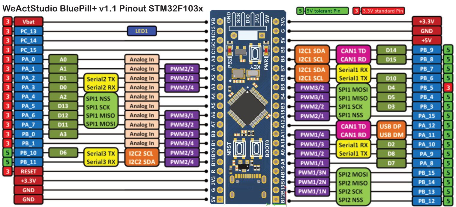
Here is the pinout for the WeActStudio BluePill Plus, it is almost identicle the a standard bluepill, with the following changes:
- No jumpers, it uses buttons to select boot modes; Reset, and Boot0
- USB-C connector
- User defined KEY button (Momentary NO connected to PA0)
- Included a proper pull-up resistor for DFU
- On-board 16MB SPI Flash
- a few extra GPIOs exposed
- SWD debug header with full pinout
- If they uploaded the bootloader you may be able to use USB DFU out of the box
Connecting the board
We will assume the need for an ST-LInk V2 here, although you may be able to get away with direct USB. Once your pin headers are soldered to the bluepill, hook up the ST-Link GND, SCK, DIO, and 3V3 pins to the SWD pins on the bluepill.
- GND: Reference ground for signal levels
- SCK: Serial wire clock - clock line for the SWD (Serial Wire Debug) interface
- DIO: SWD IO - Data line for SWD comms
- 3V3: Vcc / VRef input/supply
Side Note: DIO can also be configured to be GPIO PA13, and DCLK as GPIO PA14.
The 3.3v input will be regulated, and unless you can locate the voltage regulator datasheet 150mA is a safe bet as the maximum. The chip will draw 50mA max which leaves 100mA of headroom if powered from the 3.3v regulator.
Follow the one power source rule 3.3v in, 5v in, USB, pick one, not more!
Power the board up and check the red/yellow power LED is lit up, a blink sequence on the PB2 LED might start (linked to pin PC13). Unplug the power.
Now hook up your ST-LINK V2 emulator, if the board powers on; open a terminal and install the open source version of the st-link software, unless you have an official st-link device, and run:
st-info --probe
If you are on Windows I recommend using windows subsystem for linux for all this development, but if you must use Windows then checkout the Windows STM32 ST-Link Utility.
If the board is not connecting correctly, the output may look like this:
Failed to enter SWD mode
Found 0 stlink programmers
  version:    V1J38S7
  serial:     26249B1C8318303030303032
  flash:      -1 (pagesize: 0)
  sram:       -1
  chipid:     0xffffffffffffffff
  dev-type:   unknown
Double check the jumper cables between your ST-LINK V2 and the pins on the bluepin match up.
If the board has been connected correctly you will recieve an output like this:
Found 1 stlink programmers
  version:    V2J38S7
  serial:     26250B1C8318303030303032
  flash:      131072 (pagesize: 1024)
  sram:       20480
  chipid:     0x410
  dev-type:   STM32F1xx_MD
Check the dev type is correct, here we have a STM32F1xx chip reported which is great, we can also see the board has 20K of SRAM and 128K of flash, yours may have 64K of flash if it is a C8T6 version.
You can also read, write, and erase the flash memory directly with the st-link tools using st-flash command, which we will touch on towards the end.
libopencm3
libopencm3 is a open source hardware abstration library for the ARM chips. It is lower level than the STM32 HAL but not as unfriendly as bare metal. It’s a scaleable platform with a very reasonable license. For example; this provides a nice API for accessing the GPIO pins, dealing with tickers, and setting interupts.
To build the library you will need to install an arm toolchain such as gcc-arm-embedded which can also be done via apt in linux. See my Getting Started with Embedded post for an explanation of all the different ARM tool chains and where they fit in.
Once the Arm toolchain is installed, head over to the libopencm3 github and follow the setup wiki, they have some important notes about keeping the current implementation of libopencm3 in your project dirs as it is under heavy development rather than installing a global one, and infact after some more reading they suggest using the libopencm3-template git repo to use libopencm3 in your own projects
For me, that means creating a new directory and running a git clone inside it:
git clone --recurse-submodules git@github.com:libopencm3/libopencm3-template.git blinky-cbt6
The reason for adding it as a git submodule is that git will differentiate the library from your project so merging library updates / modifications you make to the library will be easier later on. Libopencm3 recommend adding the library as a submodule to each project as the lirbrary is still in flux and so installing globally is not recommended.
cd inside the new blinky-cbt6 directory and you can compile libopencm3 with:
make -C libopencm3
This will take a little bit of time, and only needs to be done once. This is a very modular template and can be used for many different boards. You have just compiled libopencm3! It is all nicely contained within the libopencm3 directory, and already has the nessecary files and strucutre to link it to your project. This is adaptable for many chips, not only the STM32F1 series.
Inside blinky-cbt6 if you run a “ls” command you should see a few things in addition to the libopencm3 directory, cd into the my-project dir and you should find a Makefile, open that up in text editor of choice (neovim for me), the Makefile looks like this:
PROJECT = awesomesauce
BUILD_DIR = bin

SHARED_DIR = ../my-common-code
CFILES = my-project.c
CFILES += api.c
AFILES += api-asm.S

# TODO - you will need to edit these two lines!
DEVICE=stm32f407vgt6
OOCD_FILE = board/stm32f4discovery.cfg

# You shouldn't have to edit anything below here.
VPATH += $(SHARED_DIR)
INCLUDES += $(patsubst %,-I%, . $(SHARED_DIR))
OPENCM3_DIR=../libopencm3

include $(OPENCM3_DIR)/mk/genlink-config.mk
include ../rules.mk
include $(OPENCM3_DIR)/mk/genlink-rules.mk
Let’s edit the PROJECT, CFILES, DEVICE, and 00CD_File parameters as suggested by the comments:
PROJECT = blinky
CFILES = main.c
DEVICE=stm32f103cb
OOCD_FILE = board/stm32f1x.cfg
Write and quit that file.
Blinky
Within the my-project directory create and open a new file called main.c, inside here we will first call the main libopencm3 HAL for the board, and the HAL for accessing the GPIO pins:
#include <libopencm3/stm32/rcc.h>
#include <libopencm3/stm32/gpio.h>
Then we will run a very minial blinky loop, first lets take a look at where the onboard LED is,or you can use your own external one. On my board there is a silk screen print saying “PB2” which suggests the LED is on GPIO group B, pin 2. The Cortex M chips do not activate all the GPIO pins by default to save power, they are grouped, and you must enable the group you want, along with enabling the clock, and selecting an appropriate clock speed:
int main(void) {

    // Enable the clock for GPIO port B via RCC (Reset & Clock control)
    // This is defined in the libopencm3/stm32/rcc.h file
    rcc_periph_clock_enable(RCC_GPIOB);

    // Set the PB2 pin as an output pin, in push-pull mode, using the 2 MHz clock
    // This is defined in the libopencm3/stm32/gpio.h file
    gpio_set_mode(GPIOB, // Which GPIO port to target
                  GPIO_MODE_OUTPUT_2_MHZ, // The output singla clock (alternatives: 10 & 50 Mhz)
                  GPIO_CNF_OUTPUT_PUSHPULL, // Sets the pin as a push-pull output
                  GPIO2 // The pin to set on the GPIO port.
                  );

    // Blink loop
    while(1) {

        // Toggle the logic level of the pin, high becomes low and vice versa
        // Defined in libopencm3/stm32/gpio.h
        gpio_toggle(GPIOB, GPIO2);
        for (int i = 0; i < 500000; i++) {__asm__("nop");}
        }
    }
This loop uses the no-operation assembly instruction __asm__("nop") which literaly inserts a NOP into the compiled code, it is not efficient but gets the point across and will make the device blink, although it will not be able to do anything else in the mean time, a true delay.
For clarity, here is the full main.c file:
#include <libopencm3/stm32/rcc.h>
#include <libopencm3/stm32/gpio.h>

int main(void) {
    rcc_periph_clock_enable(RCC_GPIOB);
    gpio_set_mode(GPIOB, GPIO_MODE_OUTPUT_2_MHZ,
                  GPIO_CNF_OUTPUT_PUSHPULL, GPIO2);

    while (1) {
        gpio_toggle(GPIOB, GPIO2);
        for (int i = 0; i < 200000; i++) { __asm__("nop"); }
    }
}
Now save and quit out of the file, and run the make command.
This will generate all the necessary files to flash onto the device. If you make changes the main.c and Make does not recognise them, check in the Makefile that you have the correct filename for the CFILES parameter.
Run an ls command in the terminal and you’ll now see some new files in the directory, note blinky.bin, this is our program to flash onto the board.
Flash onto the board
In the terminal use the ST utility tool we installed earlier to write blinky.bin to the flash of the device:
st-flash write blinky.bin 0x8000000
You should now see the board blinking, if it is a bit too similar to the blinky that came shipped with the board, go back into your main.c, change the timing of the delay, quit and save the file, run the make command inside your my-project directory, then the st-flash command from above again and see if the light has changed pace, if it hasn’t well… goodluck!
Learning libopencm3
The documentation is quite poor, nothing like the STM32 HAL, so the first port of call here is sniffing around the files inside libopencm3/include/libopencm3/stm32/ and f1/ to find the functions and registry level details.
Check out the RM0008 Reference Manual too from ST for the STM32F103 chip for GPIO registers, RCC setup, pin modes etc. Libopencm3 wraps these registers up into functions which are easier to use.
If you are trying to understand what a function does then running a grep for it is often the fastest way to find the details:
grep -R gpio_toggle libopencm3/include
and finally make sure to checkout the libopencm3 git
Copyright © 2025 David O’Connor