STM32 #2 Nucleo L152RE Blinky with PlatformIO and STM32Cube Framework
The blinky is great for testing out various toolchains, IDEs and boards, a sanity check, does everything work, are my cables and connections good. So as I test new tools or switch boards I might throw the blinky for them here, including the issues I run across…
Blinky on the Nucleo L152RE
I had this board lying around and it happened to be using a ARM Cortex M3 which is something I am interested in learning the architecture for. So I started with some basic guides from the stm-base project mentioned in the previous post.
VSCode + PlatformIO
To make the initial launch not too eye watering I decided to use an IDE (VSCode) that I was familiar with and has a nice extension (PlatformIO IDE) which streamlines the pipeline needed to get code on to the board.
The nucleo board comes with a ST-Link V2 attached to the board so you can connect it directly via the usb port, or you can grab an ST-Link V2 separately and wire it up to the 4 SWD pins on CN4, or directly via the GPIOs §(just remeber to set the jumpers correctly on CN2 (all removed) so that the embedded ST Link on the board is bypassed. Generally if there are communication problems, check all the jumpers are configured correctly! If still having issues, try a different usb cable/ST-Link! Here is the (STLink documentation
Bootup VSCode with the platformIO extension installed and click the Alien (PlatformIO) buttom on the left hand side(normally), wait for it to load then select “platforms” then “embedded”, here search for “ST STM32” and make sure that is installed.
Click devices and search for Nucleo L152RE, select the board and it will take you to the platofromIO page for that board with explanations of what hardware to use with the board, along with compatible configurations and frameworks supported by PlatformIO.
Setting up a project
Within the platform IO vscode extension navigate to “Projects” and select “Create New Project” then input these options:
- Your project name (I often put the SoC model in here for reference in the future)
- Board: ST Nucleo L152RE (if this is not present scroll up and follow instructions for adding the board to PlatformIO)
- Framework: STMCube (this is not my preference, but good for a first blinky as there are lots of resourced online for this implementation)
Hit create
You are met with a bunch of directories under your new project in the explorer panel (usually on the left hand side):
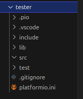
Select platformio.ini and add ‘’’ upload_protocol = stLink ‘’’
now select src and create a new file called main.c
The first thing you need to specify is which HAL library you want to use, these are made by ST to work with their hardware, they link the SoC to to the peripherals on the board such as GPIO pins.
#include <stm32l1xx_hal.h>
#include <stm32l1xx_hal_gpio.h>
The first hal give access to important functions such as delay, system clock, and peripheral control, the second “…hal_gpio.h” gives access to functions to setup and toggle gpio pins for the board.
Then we define which GPIO pins that the onboard LED are connected to, or which pins you have connected an external LED to.
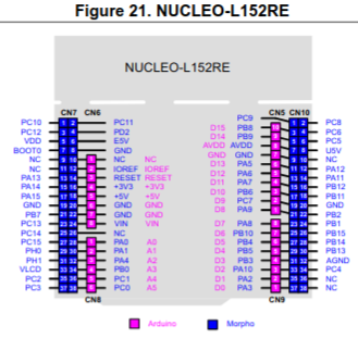
For the onboard LED this is not straight forward, if you look at the ST User Manual for the board (UM1724) and search for LED2 (as labeled on the board), you will find this: “Green user LED LD2 is connected to D13 of ARDUINO® signal.” So now how do you address the D13 ardunio pin? Well if you search for D13 you will find some pinout conversion charts, look for the L152RE specific one and you will find it is mapped to PA_5:
There are a lot of GPIO pins on the L152RE board, and as this is a low power chip so it tries to be efficient by not automatically activating them all. They are grouped, and you must tell the SoC to activate the group that PA_5 is on (GPIOA in this case), additioanlly to that you want to also enable the internal clock for that GPIOA group so we can count for the blinking, so now lets define three variables for this:
#define LED_PIN                 GPIO_PIN_5 // Arduino D13 = L152RE PA5
#define LED_GPIO_PORT           GPIOA
#define LED_GPIO_CLK_ENABLE()   __HAL_RCC_GPIOA_CLK_ENABLE()
Lets write a function to initialise those pins:
void LED_Init() {
    LED_GPIO_CLK_ENABLE();                      // Enables the GPIOA clock
    GPIO_InitTypeDef GPIO_InitStruct;           // defines strcutre for configuring GPIO pins
    GPIO_InitStruct.Pin = LED_PIN;              // set the LED pin (PA5)
    GPIO_InitStruct.Mode = GPIO_MODE_OUTPUT_PP; // Set the pin to be an output push-pull mode
    GPIO_InitStruct.Pull = GPIO_PULLUP;         // Set it to use a pull up resistor
    GPIO_InitStruct.Speed = GPIO_SPEED_HIGH; // Another power saving feature: the GPIO pins default to a low frequency, so set it to high frequency
    HAL_GPIO_Init(LED_GPIO_PORT, &GPIO_InitStruct); // Apply the settings to GPIOA
}
Now write a small function that tells the HAL to start counting cycles, this gets called automatically every 1ms by the systick timer interrupt and will increment the HALs internal tick counter for use with the HALs delay function.
void SysTick_Handler(void) {
    HAL_IncTick();
}
Run the LED_Init function:
void LED_Init();
And now write the “main” loop which will handle setting the LED on or off, this uses the delay function from the ST HAL which invokes interupts rather than actually delaying the entire MCU, and flashes the led fash 5 times, then slow 5 times, before repeating, this way you can distinguish between this code and a default blinky if one is already active on the board:
int main(void) {
    HAL_Init(); // initialise the HAL library
    LED_Init(); // Call our function to initialise the LED pin

    int i;

    while (1)
    {
        for (i=0; i<5; i++) {
            HAL_GPIO_TogglePin(LED_GPIO_PORT, LED_PIN);
            HAL_Delay(500);
        }
        for (i=0; i<5; i++) {
            HAL_GPIO_TogglePin(LED_GPIO_PORT, LED_PIN);
            HAL_Delay(2000);
        }
    }
}
Now you are ready to click build or Ctrl + Alt + B. If the code compiles, make sure you have the board connected via an STLink and hit upload or Ctrl + Alt + U. If it did not compile, here is the full code:
#include <stm32l1xx_hal.h>
#include <stm32l1xx_hal_gpio.h>

#define LED_PIN                 GPIO_PIN_5 // Arduino D13 = L152RE PA5
#define LED_GPIO_PORT           GPIOA
#define LED_GPIO_CLK_ENABLE()   __HAL_RCC_GPIOA_CLK_ENABLE()

void LED_Init();

int main(void) {
    HAL_Init();
    LED_Init();

    int i;

    while (1)
    {
        for (i=0; i<5; i++) {
            HAL_GPIO_TogglePin(LED_GPIO_PORT, LED_PIN);
            HAL_Delay(500);
        }
        for (i=0; i<5; i++) {
            HAL_GPIO_TogglePin(LED_GPIO_PORT, LED_PIN);
            HAL_Delay(2000);
        }
    }
}

void LED_Init() {
    LED_GPIO_CLK_ENABLE();
    GPIO_InitTypeDef GPIO_InitStruct;
    GPIO_InitStruct.Pin = LED_PIN;
    GPIO_InitStruct.Mode = GPIO_MODE_OUTPUT_PP;
    GPIO_InitStruct.Pull = GPIO_PULLUP;
    GPIO_InitStruct.Speed = GPIO_SPEED_HIGH;
    HAL_GPIO_Init(LED_GPIO_PORT, &GPIO_InitStruct);
}

void SysTick_Handler(void) {
    HAL_IncTick();
}
Lastly, you can also open up a serial monitor to read or communicate with the device, go into the platformio.ini and add this line:
monitor_speed = 115200
compile and upload that, then hit Ctrl + Alt + M to bring up a serial monitor.
Copyright © 2025 David O’Connor